3 mounting specifications, Chapter 3 - installation and connection – Xylem SSW-07 Soft-Starter User Manual
Page 14
CHAPTER 3 - INSTALLATION AND CONNECTION
13
English
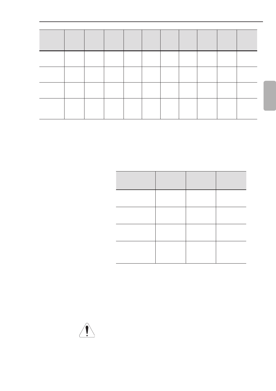
table 3.1 - Installation data with dimensions in mm (in)
To install the Soft-Starter SSW-07 leave at least the free spaces
surrounding the Soft-Starter as in figure 3.2 below. The dimensions
of these free spaces are described in table 3.2.
SSW-07 Model
A
mm
(in)
B
mm
(in)
C
mm
(in)
17 A
24 A
30 A
50
(2)
50
(2)
30
(1.2)
45 A
61 A
85 A
80
(3.2)
80
(3.2)
30
(1.2)
130 A
171 A
200 A
100
(4)
100
(4)
30
(1.2)
255 A
312 A
365 A
412 A
150
(6)
150
(6)
30
(1.2)
table 3.2 - Recommended free spaces
Install the Soft-Starter SSW-07 in the vertical position according to
the following recommendations:
1) Install on a reasonably flat surface;
2) Do not put heat sensitive components immediately above the
Soft-Starter SSW-07.
ATTENTION!
If a Soft-Starter SSW-07 is installed on top of another use the
minimum distance A + B and diverge from the top Soft-Starter the
hot air that comes from the one beneath it.
3.1.3 Mounting
Specifications
* IP20 with optional.
SSW-07
Model
Height
H
mm
(in)
Width
L
mm
(in)
Depth
P
mm
(in)
A
mm
(in)
B
mm
(in)
C
mm
(in)
D
mm
(in)
Mounting
Screw
Weight
kg
(lb)
Degree
of
Protection
17 A
24 A
30 A
162
(6.38)
95
(3.74)
157
(6.18)
85
(3.35)
120
(4.72)
5
(0.20)
4
(0.16)
M4
1.3
(2.9)
IP20
45 A
61 A
85 A
208
(8.19)
144
(5.67)
203
(7.99)
132
(5.2)
148
(5.83)
6
(0.24)
3.4
(0.13)
M4
3.3
(7.28)
IP20
130 A
171 A
200 A
276
(10.9)
223
(8.78)
220
(8.66)
208
(8.19)
210
(8.27)
7.5
(0.3)
5
(0.2)
M5
7.6
(16.8)
IP00 *
255 A
312 A
365 A
412 A
331
(13.0)
227
(8.94)
242
(9.53)
200
(7.87)
280
(11.0)
15
(0.59)
9
(0.35)
M8
11.5
(25.4)
IP00 *