Xylem P81875F Series HSC and HSC-S Centrifugal Pump User Manual
Page 29
15. Cool the bearing to room temperature and coat both
sides with two or three ounces of recommended grease.
16. Coat the inside of the bearing housing (3-025-4) with
grease and slide into place over bearing. Attaching the
bearing housing to the stuffing box with four capscrews
(3-904-9).
17. Repeat steps for inboard side of rotating element.
NOTE: A snap ring is not installed on the inboard end of
the shaft.
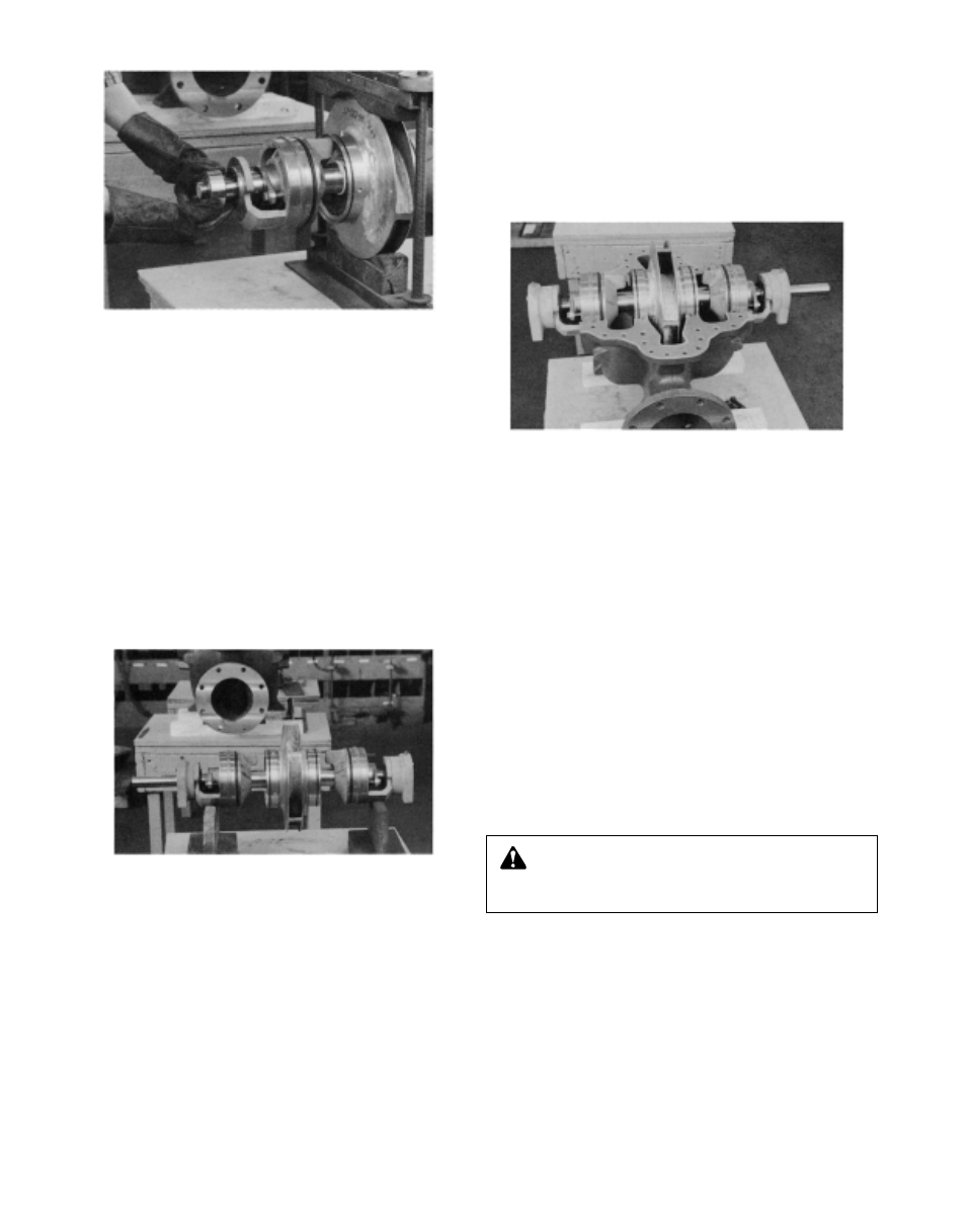
18. Set the rotating element in the pump casing. Locate both
stuffing box tongues in their respective casing grooves.
Locate pins in stuffing box and wear rings in their respec-
tive slots at the casing parting surface. Correct any
excessive “O” ring buckling (See Photo 30).
NOTE: Do not cut or damage “O” rings when lowering the
rotating element into position. When all four pins are cor-
rectly located, there will be some casing ring looseness.
19. Install a new 1/64 inch thick gasket with a light coat of
commercial cup grease on both gasket surfaces.
IMPORTANT: Align the inner edge of the gasket with the
stuffing box “O” rings.
20. Lower the upper half casing (2-001-7) into place and
install casing joint bolts (2-904-1 and -2).
IMPORTANT: When installing upper half casing, assure
that “O” rings are not cut or pinched.
21. Insert tapered casing joint dowels (2-916-1), and drive
them home.
22. Tighten the joint bolts to the following torque values: 140
ft.-lb. minimum for
5
/
8
"-11 hex head capscrews (Grade 5);
350 ft.-lb. minimum for
7
/
8
"-9 Ferry Cap Countr-bor
screws (Grade 8). The bolt torque pattern is shown in
Illustration 10.
23. Rotate the shaft by hand to assure that it turns smoothly
and is free from rubbing or binding.
24. Install coupler and align. Replace coupler guard, see
separate instructions on page 29.
25. Install 12 full rings of packing (6 per stuffing box) so that
the ends butt, leaving no gap between the packing and
the stuffing box.
26. Assemble the glands, washers, and bolts square with the
stuffing box and pull tight. Then loosen the gland bolts to
permit the packing to expand. Then re-tighten finger tight.
Final adjustment of the gland bolts must be done with the
pump running. Allow 30 minutes between adjustments. A
good adjustment should allow approximately one drip per
second.
WARNING: Rotating Components Hazard
Do not operate pump without all guards in place.
Failure to follow these instructions could result in serious
personal injury or death and property damage.
Photo 30 – Rotating Element
(Packing Installed)
Photo 31 – Upper Casing Half Removed
Photo 29 – Installing Shaft Bearing
2