Xylem P81875F Series HSC and HSC-S Centrifugal Pump User Manual
Page 21
11. Slide the deflector over the shaft end; then push the shaft
end through the oil seal and slide stuffing box fully onto
the shaft. DO NOT COMPRESS THE SEAL SPRING AT
THIS TIME.
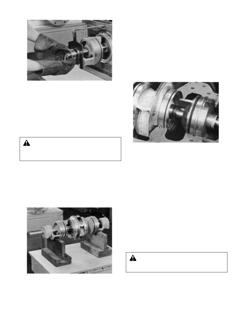
12. Heat ball bearing (3-026-4), using either dry heat or a 10
to 15% soluble oil and water solution.
IMPORTANT: Do not exceed 275°F.
13. Using gloves, press the heated bearing onto the shaft
against the shaft shoulder (See Photo 9).
14. Install snap ring (3-915-4) (or locknut and lockwasher) on
the outboard end of the shaft.
15. Cool the bearing to room temperature and coat both
sides with two or three ounces of recommended grease.
16. Coat the inside of the bearing housing (3-025-4) with
grease and slide into place over bearing. Attaching the
bearing housing to the stuffing box with four capscrews
(3-904-9).
17. Repeat steps 9 through 13, 15 and 16, including
IMPORTANT NOTE in step 8, for inboard side of rotating
element.
NOTE: A snap ring is not installed on the inboard end of
the shaft.
18. Set the rotating element in the pump casing. Locate both
stuffing box tongues in their respective casing grooves.
Locate pins (3-943-9) in stuffing box and wear rings in
their respective slots at the casing parting surface.
Correct any excessive “O” ring buckling (See Figure 16).
NOTE: Do not cut or damage “O” rings when lowering the
rotating element into position. When all four pins are cor-
rectly located, there will be some casing ring looseness.
19. Install a new
1
/
64
inch thick gasket with a light coat of
commercial cup grease on both gasket surfaces.
IMPORTANT: Align the inner edge of the gasket with the
stuffing box “O” rings.
20. Lower the upper half casing (2-001-7) into place and
install casing joint bolts (2-904-1 and -2).
IMPORTANT: When installing upper half casing, assure
that “O” rings are not cut or pinched.
21. Insert tapered casing joint dowels (2-916-1), and drive
them home.
22. Tighten the casing joint bolts to the following torque
values: 140 ft.-lb. minimum for
5
/
8
"-11 hex head cap-
screws (Grade 5); 350 ft.-lb. minimum for
7
/
8
"-9 Ferry Cap
Countr-bor screws (Grade 8). The bolt torque pattern is
shown in Illustration 10 on page 12.
23. Rotate the shaft by hand to assure that it turns smoothly
and is free from rubbing or binding.
24. Install coupler and align. Replace coupler guard, see
separate instructions on page 00.
2
£
CAUTION: Extreme Temperature and/or
Flying Debris Hazard
Eye protection and gloves required. Failure to follow these
instructions could result in property damage and/or moder-
ate personal injury.
WARNING: Rotating Components Hazard
Do not operate pump without all guards in place.
Failure to follow these instructions could result in serious
personal injury or death and property damage.
Photo 11 – Upper Casing Half Removed
Photo 9 – Installing Shaft Bearing
Photo 10 – Rotating Element