Xylem P81875F Series HSC and HSC-S Centrifugal Pump User Manual
Page 19
1
Remove coupler guard (see separate instructions on page
29) and disconnect coupler.
Remove external tubing (1-939-9) if supplied.
2. Loosen but do not remove main joint capscrews (2-904-1
and 2-904-2). Insert a screwdriver or pry bar into the slots
between the upper and lower casing halves – separate
joint.
3. Remove all casing main joint capscrews and dowels
(2-916-1), lift off the upper casing half.
4. Tap the stuffing boxes with a soft-headed hammer to
break the seal between the stuffing box and lower casing
half, and lift the rotating element out of the lower casing.
NOTE: A spare rotating element can be installed at this
point.
5. Remove four capscrews (3-904-9) from each bearing
housing (3-025-3 and 3-025-4) and remove the bearing
housings from the shaft.
6. Remove snap ring (3-915-4) (or locknut and lockwasher
on pumps built after 1991) from the outboard end of the
shaft and, using a puller, remove the bearing (3-026-4)
from the shaft. Remove the drive end bearing in the same
manner.
NOTE: Snap ring is not used on drive end bearings.
IMPORTANT: Do not reuse the ball bearings.
7. Slide stuffing boxes (3-073-9) off of the shaft, working
deflector ring (3-136-9) off the shaft at the same time.
8. Drive oil seal (3-177-9) from the stuffing box.
9. Drive mechanical seal seat (3-401-0) from the stuffing
box.
10. Remove two casing rings (3-003-9) from the impeller
(4-002-0) and remove “O” ring (3-914-9) and locating pin
(3-943-9) from each casing ring.
11. Remove mechanical seal head (3-402-0) from the pump
shaft.
12. Remove the impeller retaining ring (3-915-1) with a retain-
ing ring pliers (Photo 5). Heat the impeller hub on both
ends to 350°F maximum, and pull or push the impeller
from the shaft.
NOTE: For impellers with replaceable rings – remove the rings
(4-004-9) by cutting the rings with a cold chisel.
CAUTION: Excessive Pressure Hazard
Make certain the internal pressure is relieved before
continuing. Failure to follow these instructions could result
in serious personal injury or death and property damage.
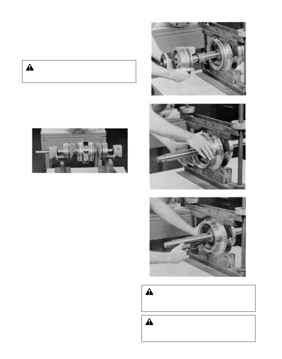
Figure 29 – Rotating Element
Photo 3 – Removing Stuff Box
Photo 4 – Removing Casing Rings from Impeller
Photo 5 – Removing Impeller Retaining Ring
CAUTION: Extreme Temperature and/or
Flying Debris Hazard
Eye protection and gloves required. Failure to follow these
instructions could result in property damage and/or moder-
ate personal injury.
CAUTION: Extreme Temperature and/or
Flying Debris Hazard
Eye protection and gloves required. Failure to follow these
instructions could result in property damage and/or moder-
ate personal injury.