Terms and usable formulas – Xylem Wastewater (Technical Manual) User Manual
Page 15
PAGE 15
Wastewater
Goulds Water Technology, Bell & Gossett,
Red Jacket Water Products, CentriPro
BASIC FORMULAS AND SYMBOLS
The term “head” by itself is
rather misleading. It is com-
monly taken to mean the dif-
ference in elevation between
the suction level and the
discharge level of the liquid
being pumped. Although this
is partially correct, it does not
include all of the conditions
that should be included to give
an accurate description.
■
Friction Head:
The pressure expressed in
lbs./sq. in. or feet of liquid
needed to overcome the
resistance to the flow in the
pipe and fittings.
■
Suction Lift: Exists when
the source of supply is
below the center line of the
pump.
■
Suction Head: Exists when
the source of supply is
above the center line of the
pump.
■
Static Suction Lift:
The vertical distance from
the center line of the pump
down to the free level of the
liquid source.
■
Static Suction Head:
The vertical distance from
the center line of the pump
up to the free level of the
liquid source.
■
Static Discharge Head: The
vertical elevation from the
center line of the pump to
the point of free discharge.
■
Dynamic Suction Lift:
Includes static suction lift,
friction head loss and veloc-
ity head.
■
Dynamic Suction Head:
Includes static suction head
minus friction head minus
velocity head.
■
Dynamic Discharge Head:
Includes static discharge
head plus friction head plus
velocity head.
■
Total Dynamic Head:
Includes the dynamic
discharge head plus dy-
namic suction lift or minus
dynamic suction head.
■
Velocity Head: The head
needed to accelerate the
liquid. Knowing the velocity
of the liquid, the velocity
head loss can be calculated
by a simple formula Head =
V
2
/2g in which g is accelera-
tion due to gravity or 32.16
ft./sec. Although the velocity
head loss is a factor in figur-
ing the dynamic heads, the
value is usually small and in
most cases negligible.
See table.
Formulas
GPM =
Lb./Hr.
500 x Sp. Gr.
H
=
2.31 x psi
Sp. Gr.
H
= 1.134 x In. Hg.
Sp. Gr.
H
V
= V
2
= 0.155 V
2
2g
V = GPM x 0.321 = GPM x 0.409
A
(I.D.)
2
BHP = GPM x H x Sp. Gr.
3960 x Eff.
Eff. = GPM x H x Sp. Gr.
3960 x BHP
N
S
= N√GPM
H
3/4
H = V
2
2g
Symbols
GPM = gallons per minute
Lb.
= pounds
Hr.
= hour
Sp. Gr. = specific gravity
H
= head in feet
psi
= pounds per square inch
In. Hg. = inches of mercury
h
v
= velocity head in feet
V
= velocity in feet per second
g
= 32.16 ft./sec.
2
(acceleration of gravity)
A = area in square inches (πr
2
)
(for a circle or pipe)
ID = inside diameter in inches
BHP = brake horsepower
Eff. = pump efficiency
expressed as a decimal
N
S
= specific speed
N = speed in revolutions
per minute
D = impeller in inches
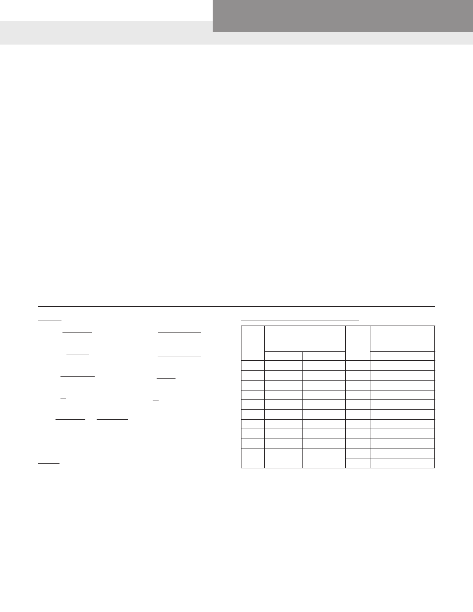
Approximate Cost of Operating Electric Motors
*Average kilowatts input
*Av. kw input or cost
Motor
or cost based on 1 cent
Motor
per hr. based on
HP
per kilowatt hour
HP
1 cent per kw hour
1 Phase
3 Phase
3 Phase
1
⁄
3
.408
20
16.9
1
⁄
2
.535
.520 25
20.8
3
⁄
4
.760
.768 30
26.0
1
1.00
.960
40
33.2
1
1
⁄
2
1.50
1.41 50
41.3
2
2.00
1.82
60
49.5
3
2.95
2.70
75
61.5
5
4.65
4.50
100
81.5
7
1
⁄
2
6.90
6.75 125
102
10 9.30
9.00
150
122
200
162
Terms and Usable Formulas