Model l, ln, 3 shaft sealing, L ln – Xylem LN User Manual
Page 50
Installation, Operating and Maintenance Instruction
Model L, LN
Page 46
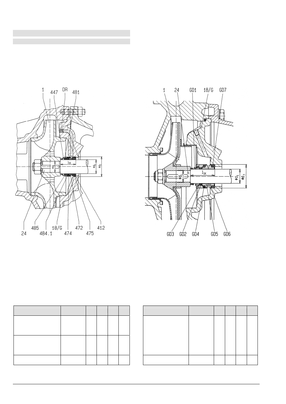
3.3 Shaft Sealing
3.3.1 Structure of the mechanical seal
This shaft seal is a single mech. seal with installation
dimensions according to EN 12756 (DIN 24960)
design "K". API plan 02 / ISO plan 00.
No additional flushing of the seal chamber is
necessary. The seal casing where the mechanical
seal is located must always be filled with liquid.
For a description of materials and operational ranges
of the mech. seals supplied, please refer to the data
sheet in the Operation Instructions and order
confirmation.
For the internal structure of the mechanical seal see
the following sectional drawings.
L LN
Index of parts:
3 Impeller
18/G Casing
cover
24 Shaft
412 Elbow
sleeve
447 Spring
472
Rotating seal ring
474 Disc
475
Stationary seal ring
483 Balg
484.1 Elbow
ring
487 Towing
DR Orifice
Index of parts:
1 Impeller
18/G Casing
cover
24 Shaft
GD1
Spring with towing effect
GD2 O-ring
(Shaft)
GD3
Rotating seal ring socket
GD4
O-ring (Rotating seal ring)
GD5
Rotating seal ring
GD6
Stationary seal ring
GD7
O-ring (Stationary seal ring)
Pump size
Bearing
bracket
d
1
d
7
d
L
l
1k
Pump size
Bearing
bracket
d
1
d
7
d
L
l
1k
L 65-315, L 80-315
L 100-160, L 100-200
L 100-250, L 100-315
L 125-250
32L
40 58 32 45
LN 32-125, LN 32-160
LN 32-200, LN 40-125
LN 40-160, LN 40-200
LN 40-250, LN 50-125
LN 50-160, LN 50-200
LN 50-250, LN 65-125
LN 65-160, LN 65-200
LN 80-160
24LN 22
37
18
37,5
L 125-200, L 125-270
L 125-315, L 150-250
L 150-315
42L
50 70 42 47,5
L 80-400, L 100-400
L 125-400, L 150-400
42L
50 70 42
118*)
LN 65-250, LN 80-200
LN 80-250
32LN 28
43
24
42,5
*) ... At these pump sizes l
1k
+spacer sleeve is 70,5mm.
The mentioned dimensions refer to mechanical seals acc. EN 12756 with length l
1k
.
Dimensions in mm without obligation! - This leaflet is subject to alteration without notice!