Xylem IMDWT R02 Model DWT Deep Well Turbine Pumps User Manual
Page 10
10
FoUNdATIoN ANd PIPING
SUB BASE (SOLE PLATE) INSPECTION
Sub base and sole plate are terms in common use to
describe a general class of solid steel plates mounted
in grout (or bolted to steel structures) at the pump-
foundation interface.
1. Remove the sub base from the pump discharge head,
when shipped assembled.
2. Completely clean the underside of the sub base. It is
sometimes necessary to coat the underside of the sub
base with an epoxy primer. (This is available as an
option.)
3. Remove the rust preventative solution from the
machined topside with an appropriate solution.
SITE WITH CONCRETE FOUNDATION
1. A pump should have adequate space for operation,
maintenance and inspection.
2. Sub base mounted pumps are normally grouted
on a concrete foundation, which has been poured
on a solid footing. The foundation must be able to
absorb any vibration and to form a permanent, rigid
support for the pumping unit.
3. The foundation must be of adequate strength to
support the complete weight of the pump, plus the
weight of the liquid passing through it. A typical
installation will have bolts with a pipe sleeve 2
1
⁄
2
times the bolt diameter embedded in the concrete.
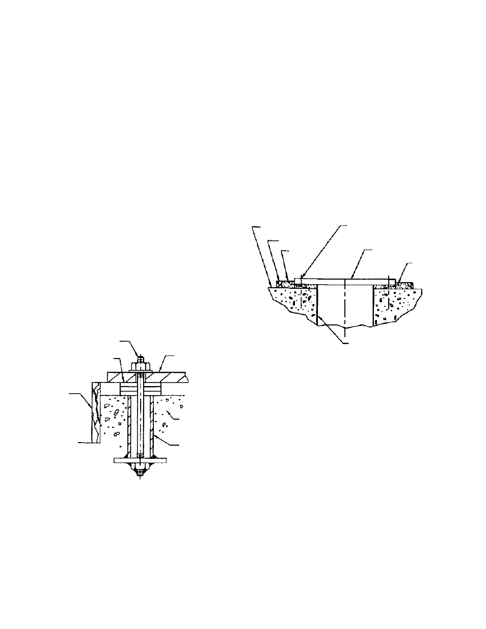
Figure 4
Bolts should be sized and located in accordance
with the dimensions given on the Certified Pump
Outline Drawing, if provided. The pipe sleeve
allows movement for the final positioning of the
foundation bolts to conform to the holes in the sub
base flange. See Figure 3.
4. Remove water and/or debris from anchor bolt holes/
sleeves prior to grouting. If the sleeve type bolts are
being used, fill the sleeves with packing or rags to
prevent grout from entering.
5. Carefully lower the sub base onto the foundation
bolts. Hand tightens the nuts.
6. Leveling the sub base may be done by several
methods. Two common methods are:
A. Using leveling the wedges. This is shown in
Figure 4.
B. Leveling nuts on the anchor bolts.
Regardless of the method, a machinist level must be
used for leveling.
NOTE: When using a machinist level, it is important
that the surface being leveled is free of all
contaminants, such as dust, to ensure an
accurate reading.
7. Level the sub base in two directions at 90 degrees
on the machined surface. The levelness tolerance
is 0.005 inches per foot for commercial, and 0.001
inches per foot for API.
Figure 5
SUB BASE GROUTING
1. Inspect foundation for dust, dirt, oil, chips, water,
etc. and remove any contaminants. Do not use oil-
based cleaners as grout will not bond to it. Refer to
grout manufacturer’s instructions.
2. Build dam around foundation (See Figure 4).
Thoroughly wet foundation.
3. Pour grout between sub base and concrete
foundation, up to level of dam. Remove air bubbles
from grout as it is poured by puddling, using a
vibrator, or pumping the grout into place. Non-
shrink grout is recommended.
4. Allow grout to set at least 48 hours.
5. Tighten foundation bolts.
PIPING
Guidelines for piping are given in the “Hydraulic
Institute Standards”, available from: Hydraulic Institute,
9 Sylvan Way, Parsippany, NJ 07054-3802 and must be
reviewed prior to pump installation.
BOLT
SHIMS
DAM
SUB BASE
FOUNDATION
SLEEVE
SUB BASE
FOUNDATION
DAM
GROUT
CENTERLINE
ANCHOR BOLT
LEVELING
WEDGES
FLOOR SLEEVE
(OPTIONAL)