Xylem IM183 R09 3AB2 & 5AB2 Aquavar ABII Variable Speed Pump Controller User Manual
Page 5
5
Motor Wires – See Table 2
NOTE: A MINIMUM OF 75ºC COPPER WIRE IS
MANDATORY.
Refer to the Table 2 for wire sizing and maximum wire
lengths. Charts are designed to limit voltage drop to 5%.
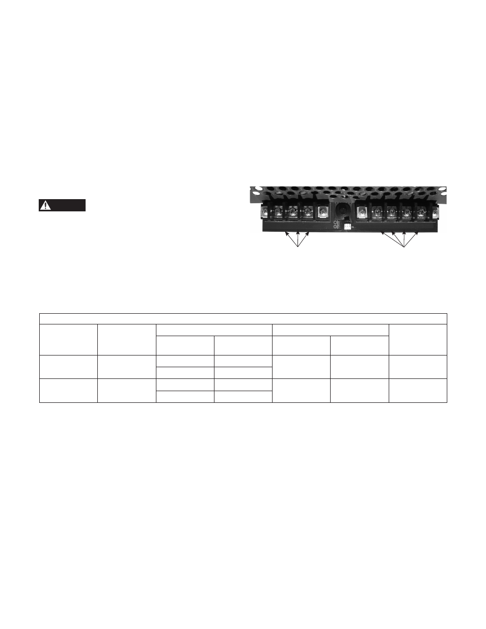
Figure 2 shows the terminal block where the motor and
input wires connect. The circuit board near the terminal
block is labeled to show where to connect the motor wires.
For all motors, the green wire from the motor must be
attached to the terminal labeled GND.
For 3Ø motors with red, black and yellow wires, connect
the red wire to RED, black wire to BLK and yellow wire to
YEL.
Note: If there is more than 50 feet of wire from the
controller to the motor, consult factory for selection of an
output load filter (load reactor).
Input Power
SHOCK OR ELECTROCUTION
HAZARD
Connect a ground wire from the service panel to the
terminal marked GND. Controller has high leakage to
ground. Controller ground terminal must be connected to
the service entrance ground terminal. Failure to do so will
result in high voltage being present on the controller chassis.
Connect two “hot” wires from the 2 pole circuit breaker to
the terminals marked L1 and L2.
The input power system used must be a grounded power
system. The voltage measured from L1 to L2 must be in the
range of 196Vac to 265Vac. The voltage measured from
L1 to GND must be equal to the voltage measured from
L2 to GND. These voltages must be within the range of
120Vac +/- 10%. Reduced input voltage will reduce system
performance.
Do not use a Ground Fault Circuit Interrupter (GFCI) with
this product or nuisance tripping will result.
Wire and Conduit
Factory installed input and output power leads may be
supplied with the controller. Use 75º C or higher rated
UL type copper wire. Use of Metal Conduit with Metal
Conduit liquid tight Connectors is recommended for all
electrical connections.
Figure 2: Wiring Connections
3Ø
L1 L2 GND
GND RED BLK YEL
Incoming Power
Wires to Motor
DANGER
Table 2
Circuit Breaker, Wire and Generator Sizing
Circuit
1Ø Input Wiring
3Ø Output Wiring*
Generator
Model
Breaker
Size
Length (ft)
Size
Length (ft) Size
(KW)
3AB2 30
10 AWG
179
14 AWG
50
8100
8 AWG
261
5AB2 50
6 AWG
244
12 AWG
50
13300
4 AWG
390
* Consult factory for selection of an output load filter (load reactor) for output wire lengths greater than 50 feet.