Pump operation guidelines – Xylem IM194 R02 GRINDER PUMPS 1 AND 3 11?4 DISCHARGE User Manual
Page 9
9
ENGINEERING DATA
PUMP OPERATION GUIDELINES
ENGINEERING DATA
Engineering data for specific models may be found in your catalog and on our website (address is on the cover).
Minimum Submergence
Continuous
Duty
Fully Submerged
Intermittent
Duty
6" Below Top of Motor
Maximum Fluid Temperature
Continuous
Operation
104º F 40º C
Intermittent
Operation
140º F 60º C
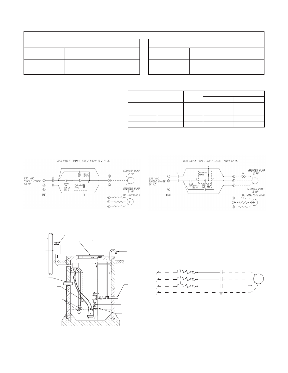
Fig. 2
L1
L2
L3
GRD
S1
Red
Black
White
Green
PUMP
Typical Three Phase Connection Diagram
TYPICAL PLUMBING AND INSTALLATION
TYPICAL PLUMBING AND INSTALLATION
SERVICE
POLE
CONTROL
PANEL
INLET GROMMET
FLOAT SWITCH
HIGH LEVEL ALARM
(OPTIONAL)
FLOAT SWITCH
ALARM LIGHT
HINGED ACCESS DOOR
VALVE
OPERATING
ROD
CHECK VALVE
LOWER
PUMP GUIDE
GUIDE
RAIL
DISCHARGE
VENT
Fig. 1
Effective with December 2005 (M05) Date Codes -
Single-Phase 1GD Pumps Contain a Built-in,
Auto Reset Overload.
Important Control Panel Requirements and Notes:
1) See panel bulletin BCP5 for other available options.
2) These pumps require a magnetic contactor, start and run capacitors
and a starting relay in the control panel.
3) CP-1GDB Capacitor packs with starting relays are available on
product bulletin BCPCAP. They are for certified panel shops to “build” into a custom panel. Field installing capacitor packs into a S10020 or D10020 will negate
the UL listing on that panel and is therefore not permissable.
Pump
Pump Seal Voltage Recommended Control Panel
Order No.
Fail Circuit / Phase
Simplex
Duplex
1GD51G1A_
NO
230 / 1
S1GD2
D1GD2
1GD51G8A_
NO
208 / 1
S1GD2
D1GD2
1GD51G1A_S
YES
230 / 1
S1GD2H
D1GD2J
1GD51G8A_S
YES
208 / 1
S1GD2H
D1GD2J
PANEL CAPACITOR WIRING DIAGRAMS
PANEL CAPACITOR WIRING DIAGRAMS
RECOMMENDED 1Ø CONTROL PANELS
RECOMMENDED 1Ø CONTROL PANELS