Instal, Final assemb, Impeller – Xylem 2000 Series Frame Mounted Pumps AC8652 REV.C User Manual
Page 16: Lation
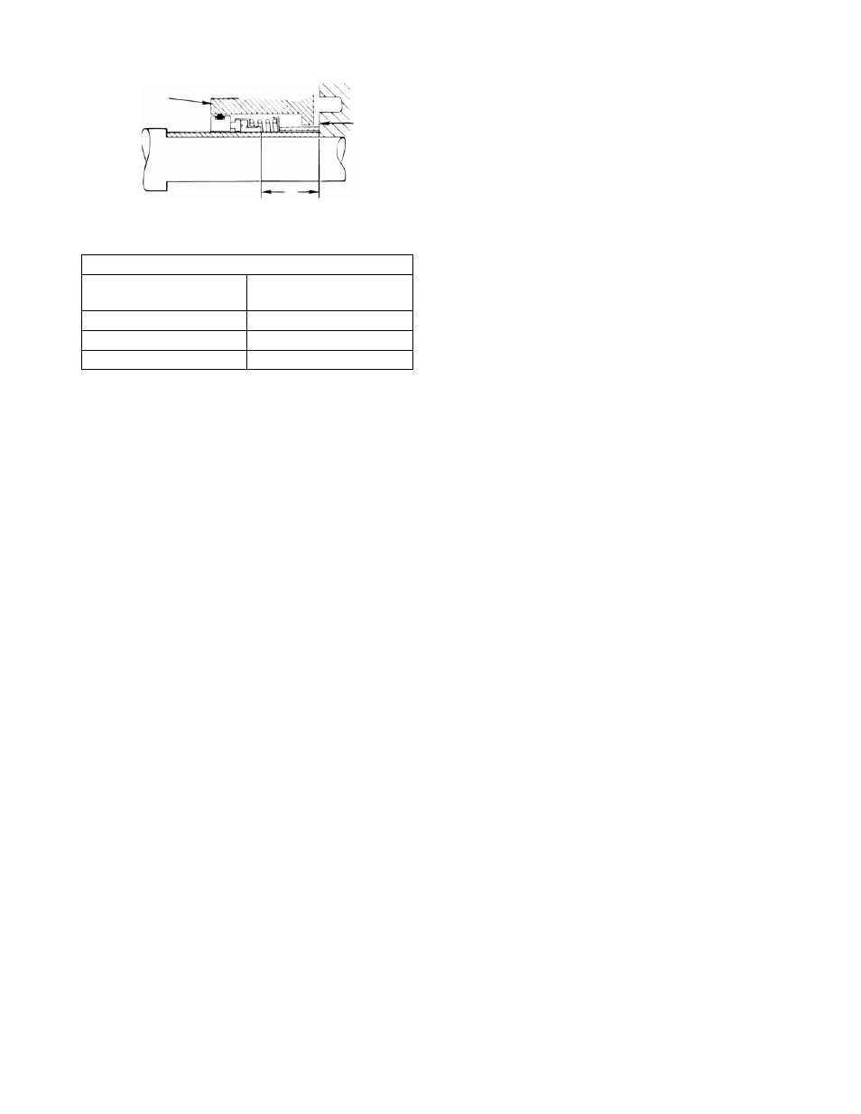
FIG. 7
“G” Setting Dimensions
Shaft Sleeve OD
(inches)
G
(inches)
1.25
1.22
1.62 1.31
2.0 1.38
7.
ith Packed Stuffing Boxes
ctor (1-136-0) onto the pump
shaft.
2.
e
e.
x
cover over the pump shaft, and, if
fing box to the
-0) into
he
he
osen the nuts to permit the
INSTAL
1.
uffing
2. Install the impelle key into the keyway on
the impeller side of the pump shaft.
3. Slide the pump impeller (4-002-0) onto the
pump shaft.
the
e
5.
FINAL ASSEMB
1. Place the O-ring casing seal (2-914-0)
a
ing box
c
e
s use capscrews and
me until
3.
4.
nect the suction and
discharge piping to the pump.
5. Connect the flush line to the stuffing box.
STUFFING
BOX
IMPELLER
HUB
Slide the deflector ring (1-136-0) onto the
motor shaft.
8. Slide the stuffing box cover, seal, and
sleeve assembly onto the frame shaft
being certain the stuffing box is closest to
the frame. To prevent any leakage, use
silicone sealant between the shaft and
shaft sleeve.
9. If applicable, bolt the frame to the stuffing
box using capscrews (1-904-0).
B. Pumps w
1. Slide defle
Slide the packing gland (6-014-0) onto th
pump shaft (flat side toward frame).
clamping lugs (2-937-0) to hold the frame
to the casing). Tighten opposite
3. Slide the shaft sleeve (1-009-0) onto the
pump shaft. To prevent leakage, use
silicone sealant between the shaft and
shaft sleev
4. Place the packing base ring (6-152-0) into
the stuffing box. Slide the stuffing bo
applicable, bolt the stuf
frame using capscrews (1-904-0).
5. Install the packing (6-924-0) and, if
applicable, the seal cage (6-013
the stuffing box being sure to stagger t
joints.
6. Tighten the packing gland nuts to seat t
packing. Lo
packing to expand then retighten finger
tight.
IMPELLER
If the pump is equipped with mechanical
seals, slide the spacer sleeve (1-154-0)
over the shaft sleeve and into the st
box.
LATION
r
4. Screw the impeller nut (4-023-0) onto
pump shaft until finger tight. Clamp th
coupling end of the pump shaft in a
padded vise, and tighten (clockwise as
viewed from the suction inlet) the impeller
nut to 25-30 ft. lbs.
For pumps with mechanical seals, tighten
gland evenly against the stuffing box.
LY
round the O-ring seat on the stu
over.
ff
2. Carefully slide the frame assembly into th
casing being sure not to pinch the O-ring.
Insert the capscrews (1-904-0) through
the frame and into the casing (the large
2000 Series pump
capscrews evenly around the fra
the stuffing box has been drawn evenly
into the casing. Then alternately torque
each capscrew to 25 lbs.
Secure frame foot to pump base.
If necessary, con
G
16