Assembly proced, Ures – Xylem 2000 Series Frame Mounted Pumps AC8652 REV.C User Manual
Page 15
ASSEMBLY PROCED
nto
sha
2.
p
apered edge away from the
3. Place snap ring (5-068-3, flat snap ring)
ositioning
aring
(5-
is
ve,
s
into
snap ring groove.
URES
FRAME ASSEMBLY
1. Press the outboard bearing (5-026-4) o
the motor side of the pump shaft
(5-007-0).
NOTE: When pressing bearings onto the
ft, press only against the inner race.
Install snap ring (5-086-0) on the pum
shaft with the t
bearing (outboard side of outboard
bearing).
over the pump shaft (5-007-0) p
the snap ring between the two be
shoulders.
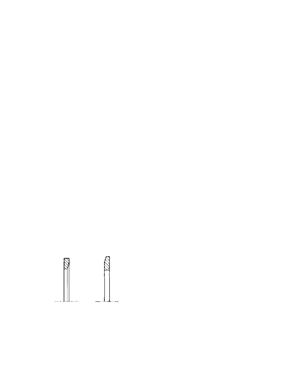
NOTE: There are two snap rings that go into
the outboard bearing housing: snap rings
068-3 and 5-068-4). Snap ring (5-068-3)
flat and goes into the inside snap ring groo
and snap ring (5-068-4) is tapered and goe
the outside
4. Press inboard bearing (5-026-3) onto the
inboard side (pump side) of the pump
shaft.
5. Press the inboard end (pump end) of the
shaft-bearing assembly into the outboard
end (motor end) of the pump frame. Press
the unit toward the pump side of the frame
until the inboard bearing clears the
outboard bearing housing.
FIG. 6 – Tapered Snap Rings
Using a suitable pair of snap ring pliers,
6.
e
the
of the outboard
7.
assembly into the frame until the outboard
-3) inside the outboard
8. Place snap ring (5-068-4) in the outside
f the outboard bearing
-4)
STU
NO
stu
one
If the pump is equipp
pos
gla
If th
stuffing box cover should be positioned so the
stu
1.
2.
stationary elements
) on the
r into stuffing box.
5.
ard stuffing box) on the stuffing box
tely 1/8" from
the stuffing box.
place snap ring (5-068-3, located on th
pump shaft between the bearings) into
inside snap ring groove
bearing housing.
Continue pressing the shaft and bearing
bearing (5-026-4) seats firmly against
snap ring (5-068
bearing housing.
snap ring groove o
housing (tapered edge away from
bearing).
9. Install bearing caps (5-018-3 and 5-018
onto both ends of the pump frame.
FFING BOX ASSEMBLY
TE: There are two pipe taps on the
ffing box; one closest to the gland, and
furthest away from the gland.
ed with mechanical
seals, the stuffing box cover should be
itioned with the pipe tap closest to the
nd on top.
e pump is equipped with packing, the
pipe tap furthest away from the gland is on
top.
For ease of assembly, install pipe fittings in
the stuffing box pipe taps before assembling
ffing box on the frame.
A. Pumps with Mechanical Seals
Install the two gland retaining studs
(6-908-0) into the stuffing box cover.
Install the rotating and
of the mechanical seal (6-400-0
shaft sleeve (1-009-0) being certain that
the two wearing surfaces face each other.
Position the seal on the sleeve according
to the “G” dimension found in Fig. 7.
3. Place seal spring retaine
4. Place seal spring into stuffing box.
Place sleeve and seal assembly into
stuffing box with rotating half of seal
installed closest to the impeller.
6. Install the seal gland (6-014-0) (flat side
tow
using the gland studs (6-908-0) and gland
nuts (6-903-0). Tighten gland nuts evenly
until the gland is approxima
5-086-0 5086-4
15