Xylem 2000 Series Frame Mounted Pumps AC8652 REV.C User Manual
Page 10
FIG
4.
to the
o same depth at 90°
um and maximum
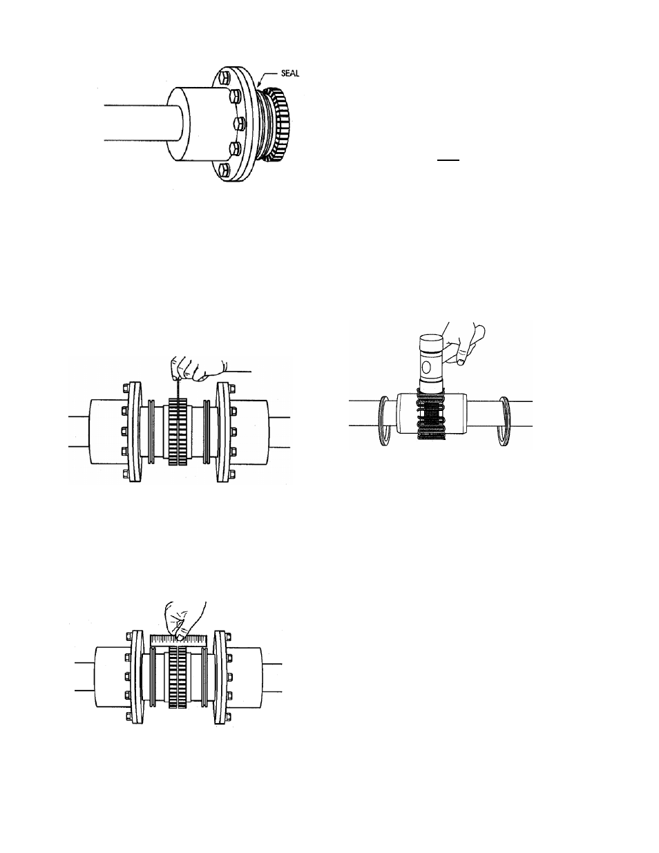
. 5D – SHAFT HUB, SEAL, & SPACER HUB
ASSEMBLY
Use a spacer bar equal in thickness
gap specified in Fig. 5J. Insert bar, as
shown below, t
intervals and measure clearance between
bar and hub face with feeler gauges. The
difference in minim
measurements must not exceed the
ANGULAR installation limits shown in
Fig. 5J.
FIG. 5E– USING SPACER BAR
5. Align so that a straight edge rest
the limits shown in Fig. 5J on both hu
shown below and also at 90° intervals.
Check with feelers. The clearance must
not exceed the PARALLEL OFFSET
installation limits specified in Fig. 5J.
s within
bs as
FIG. 5F – USING STRAIGHT
6. If adjustment is needed, loosen the motor
bolts and add (or remove) equal amounts
r each motor foot, to align
of shims unde
the height. To correct side misalignment,
strike the side of the motor foot with a
mallet. Tighten the motor bolts and check
again. If a correction is made, re-check
alignment in all directions. Repeat this
ling
wo or
nts, install them so that all cut
process until the desired result is
obtained.
7. Pack gap and grooves with coup
vendor supplied grease before inserting
grid. When grids are furnished in t
more segme
ends extend in the same direction as
shown below. This will ensure correct grid
contact with non-rotating pin in cover
halves. Spread the grid slightly to pass
over the coupling teeth and seat with a
soft mallet.
FIG. 5G – SEATING THE GRID
EDGE
10