Electrical connections – Analytical Industries GPR-1800 IS ATEX Trace PPM Oxygen Transmitter User Manual
Page 17
Advanced Instruments, Inc
17
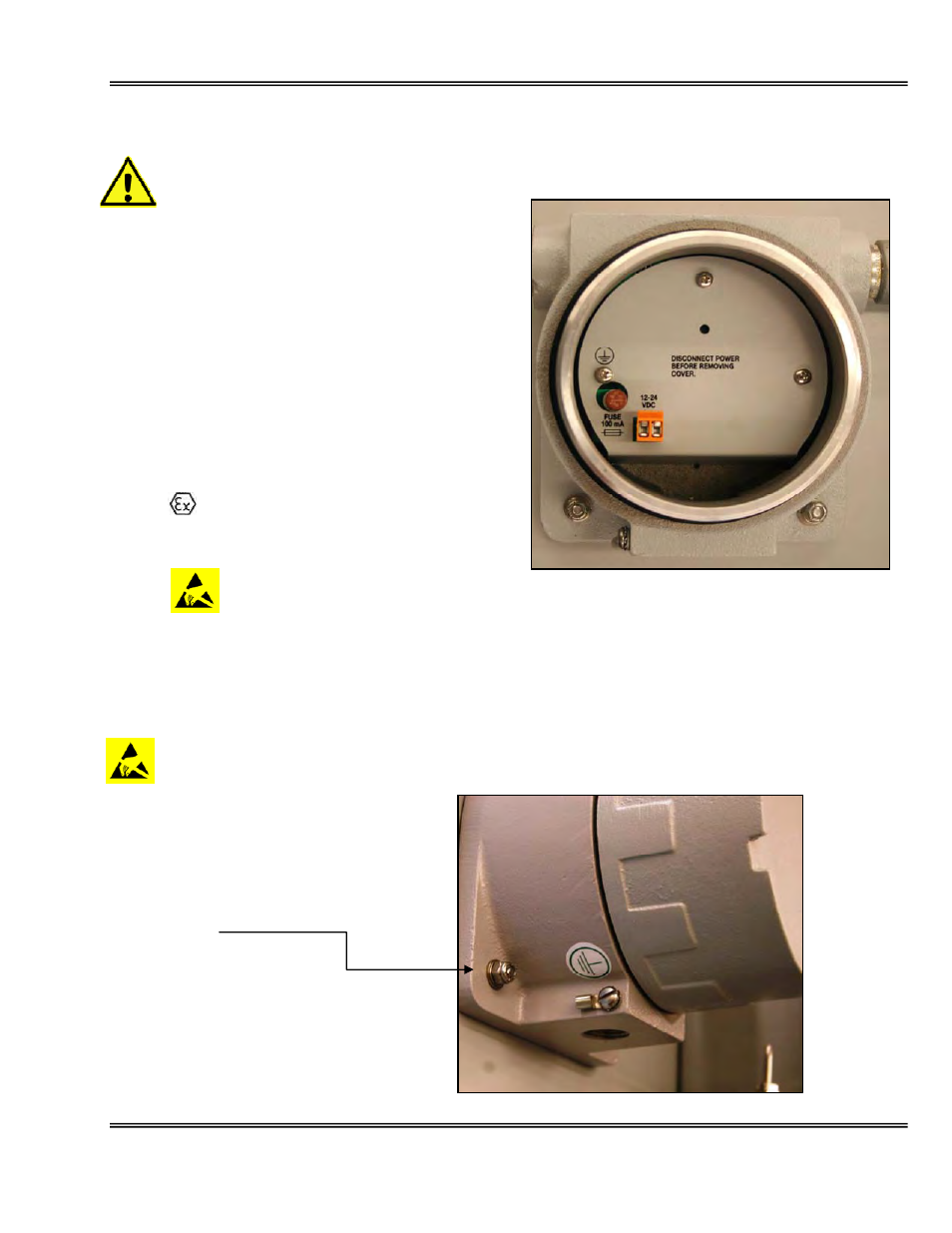
Electrical Connections
Incoming power and signal output connections are made to a terminal block mounted on a PCB
located in the explosion proof enclosure.
Do not supply voltage more than specified in this
manual and noted near the power input terminal of the
analyzer.
The PCB in the explosion proof enclosure contains a
power limiting intrinsic safety barrier that limit the total
power available at the PCB electronics mounted in the
general purpose enclosure.
With proper insulation of the incoming power (see
Appendix A), this configuration of the GPR-1800 IS
conforms to the ATEX directives for equipments for use
in hazardous area. The analyzer meets the following
area classification:
II 2 G
Ex d [ib} ib IIB T4
T
amb
-20
⁰C to +50⁰C
Ex
enclosure
for
power
input
The GPR-1800 IS also meets the intrinsic safety standards required for use in Class 1, Division 1, Group C,
D hazardous areas.
The A-1166 IS PCB in the Ex enclosure contains two fuses, one plug-in (brown color) rated at 50 mA and
the second mounted on the PCB (meets barrier network standard EN 50020).
Avoid electrostatic discharge – Clean all surfaces with a damp cloth only.
Analyzer ground terminal must be
connected to a ground