Asus G1-P7P55E User Manual
Page 47
4-6
Chapter 4: Motherboard info
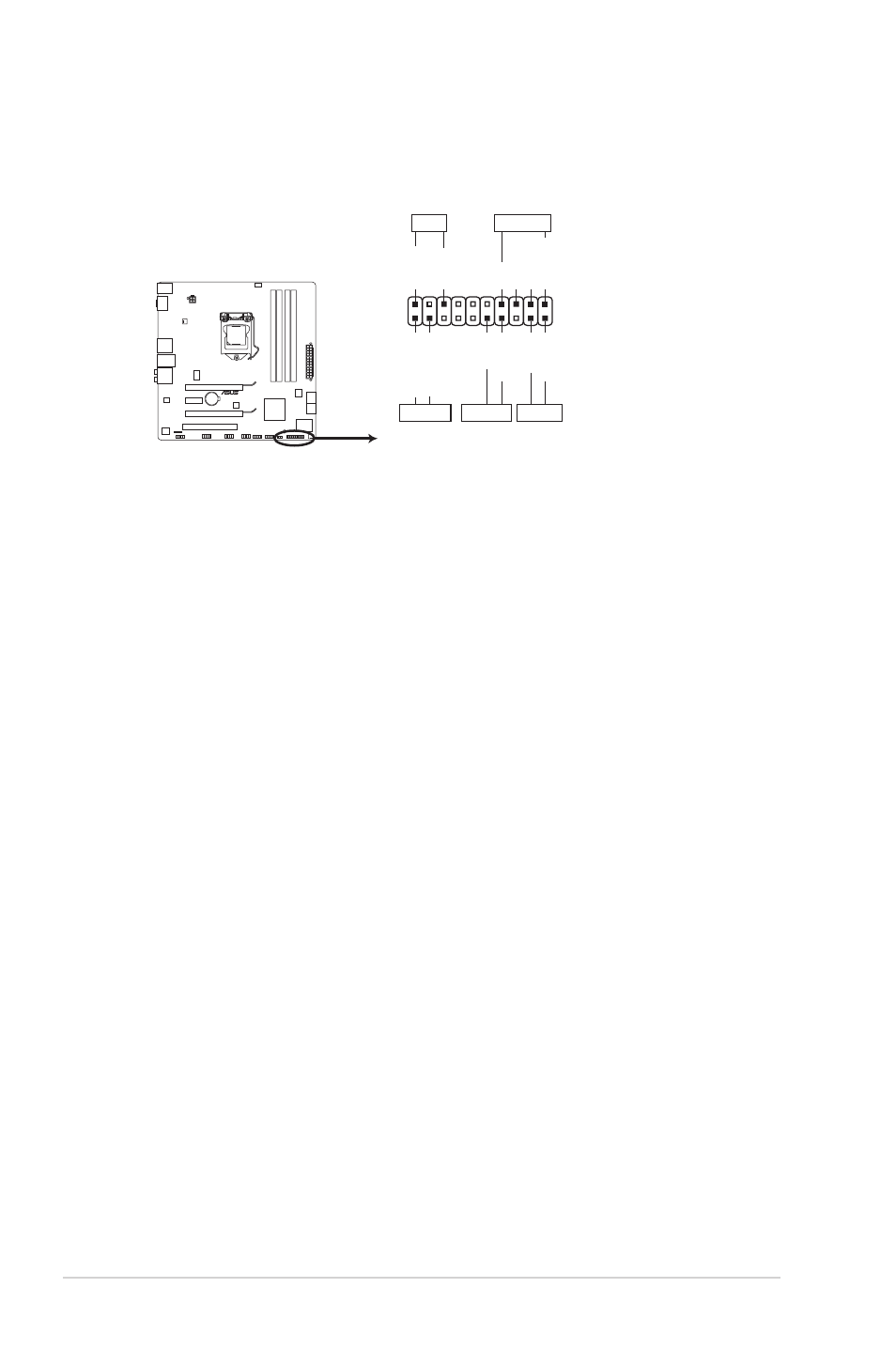
5.. System.panel.connector.(20-8.pin.PANEL)
This connector supports several chassis-mounted functions.
PIN 1
* Requires an ATX power supply
PLED
SPEAKER
PLED
+
PLED
-
+5V
Groun
d
Groun
d
Speake
r
IDE_LED
+
IDE_LED
-
PWR
Groun
d
Rese
t
Groun
d
PANEL
IDE_LED
PWRSW
RESET
P7P55-M_DP
P7P55-M_DP System panel connector
•.
System.power.LED.(2-pin.PLED)
This 2-pin connector is for the system power LED. Connect the chassis
power LED cable to this connector. The system power LED lights up when
you turn on the system power, and blinks when the system is in sleep mode.
•.
Hard.disk.drive.activity.LED.(2-pin.IDE_LED)
This 2-pin connector is for the HDD Activity LED. Connect the HDD Activity
LED cable to this connector. The IDE LED lights up or flashes when data is
read from or written to the HDD.
•.
System.warning.speaker.(4-pin.SPEAKER)
This 4-pin connector is for the chassis-mounted system warning speaker. The
speaker allows you to hear system beeps and warnings.
•.
ATX.power.button/soft-off.button.(2-pin.PWRSW)
This connector is for the system power button.
•.
Reset.button.(2-pin.RESET)
This 2-pin connector is for the chassis-mounted reset button for system
reboot without turning off the system power.