Asus G1-P5G43 User Manual
Page 21
2-5
ASUS G1-P5G43
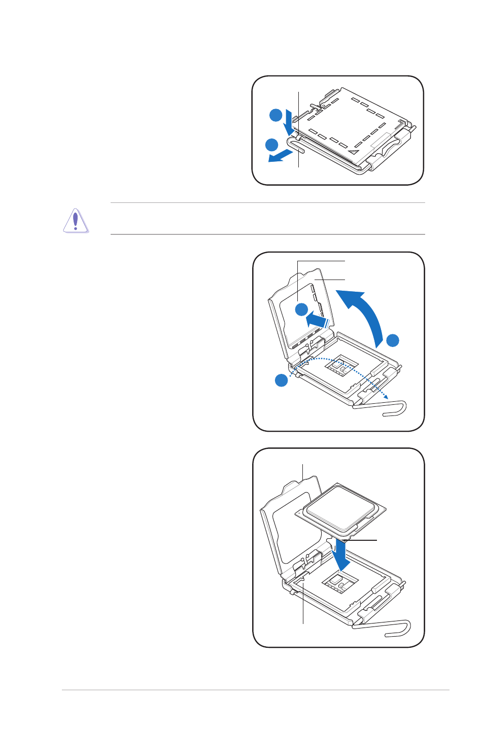
To prevent damage to the socket pins, do not remove the PnP cap unless you
are installing a CPU.
2. Press the load lever with your thumb
(A), then move it to the left (B) until it
is released from the retention tab.
3. Lift the load lever in the direction of
the arrow to a 135º angle.
A
B
Load.lever
Retention.tab
4. Lift the load plate with your thumb
and forefinger to a 100º angle (4A),
then push the PnP cap from the
load plate window to remove (4B).
5. Position the CPU over the socket,
making sure that the gold triangle
is on the bottom-left corner of the
socket then fit the socket alignment
key into the CPU notch.
Gold.
triangle.
mark
Alignment.key
CPU.notch
Load.plate
PnP.cap
4A
4B
3
See also other documents in the category Asus Computers:
- CG8565 (410 pages)
- CG8565 (246 pages)
- CS5111 (26 pages)
- CS5120 (1 page)
- ET1611PUK (38 pages)
- S2-P8H61E (80 pages)
- P2-PH1 (80 pages)
- P1-P5945G (80 pages)
- P2-P5945GCX (90 pages)
- CG8270 (218 pages)
- CG8270 (536 pages)
- CG8270 (72 pages)
- CG8270 (76 pages)
- CG8270 (534 pages)
- CG8270 (362 pages)
- P3-PH4 (80 pages)
- P3-P5G31 (100 pages)
- P2-M2A690G (80 pages)
- P2-M2A690G (8 pages)
- P4-P5N9300 (1 page)
- P4-P5N9300 (82 pages)
- P1-P5945GC (92 pages)
- P2-P5945GC (92 pages)
- P3-P5G33 (98 pages)
- T3-P5945GC (80 pages)
- T3-P5945GCX (80 pages)
- P2-M2A690G (94 pages)
- T3-PH1 (80 pages)
- T3-PH1 (82 pages)
- T5-P5G41E (82 pages)
- T5-P5G41E (76 pages)
- S1-AT5NM10E (68 pages)
- P6-P7H55E (67 pages)
- ES5000 (174 pages)
- T4-P5G43 (104 pages)
- T-P5G31 (92 pages)
- BT6130 (60 pages)
- BT6130 (54 pages)
- BT6130 (2 pages)
- CG8265 (350 pages)
- CG8265 (210 pages)
- CM1740 (330 pages)
- CM1740 (70 pages)
- CM1740 (198 pages)
- P6-M4A3000E (59 pages)