Asus P5S800-VM User Manual
Page 41
A S U S P 5 S 8 0 0 - V M
A S U S P 5 S 8 0 0 - V M
A S U S P 5 S 8 0 0 - V M
A S U S P 5 S 8 0 0 - V M
A S U S P 5 S 8 0 0 - V M
1 - 2 9
1 - 2 9
1 - 2 9
1 - 2 9
1 - 2 9
1 1 .
1 1 .
1 1 .
1 1 .
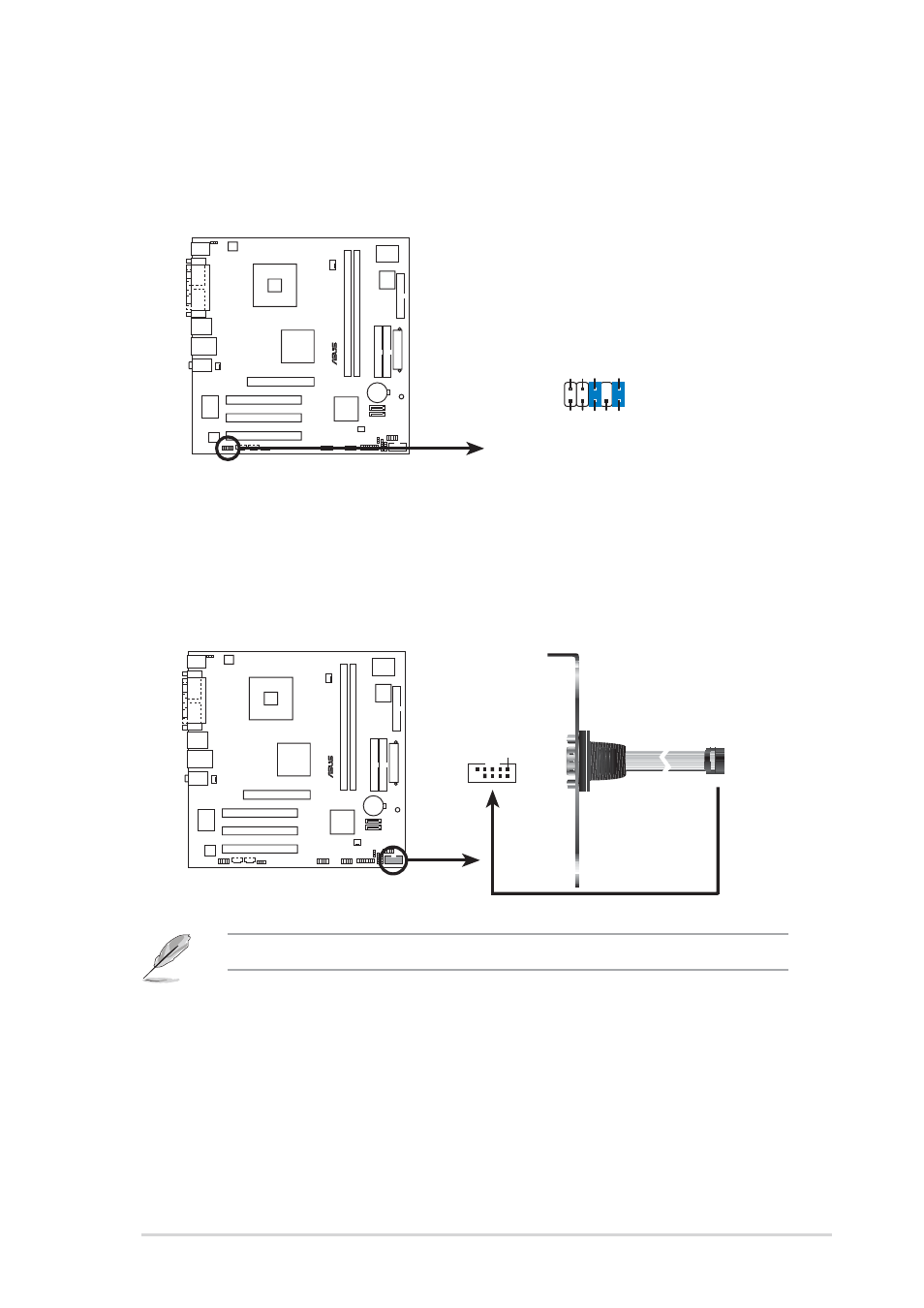
1 1 . Front panel audio connector (10-1 pin FP_AUDIO1)
F r o n t p a n e l a u d i o c o n n e c t o r ( 1 0 - 1 p i n F P _ A U D I O 1 )
F r o n t p a n e l a u d i o c o n n e c t o r ( 1 0 - 1 p i n F P _ A U D I O 1 )
F r o n t p a n e l a u d i o c o n n e c t o r ( 1 0 - 1 p i n F P _ A U D I O 1 )
F r o n t p a n e l a u d i o c o n n e c t o r ( 1 0 - 1 p i n F P _ A U D I O 1 )
This connector is for a chassis-mounted front panel audio I/O module
that supports legacy AC ‘97 audio standard. Connect one end of the
front panel audio I/O module cable to this connector.
P5S800-VM
®
P5S800-VM Front panel audio connector
FP_AUDIO1
BLINE_OUT_L
MIC2
Line out_R
Line out_L
BLINE_OUT_R
NC
MICPWR
+5V
A
AGND
P5S800-VM
®
P5S800-VM Serial port connector
PIN 1
COM2
1 2 .
1 2 .
1 2 .
1 2 .
1 2 . Serial port connector (10-1 pin COM2)
S e r i a l p o r t c o n n e c t o r ( 1 0 - 1 p i n C O M 2 )
S e r i a l p o r t c o n n e c t o r ( 1 0 - 1 p i n C O M 2 )
S e r i a l p o r t c o n n e c t o r ( 1 0 - 1 p i n C O M 2 )
S e r i a l p o r t c o n n e c t o r ( 1 0 - 1 p i n C O M 2 )
This connector is for a serial (COM) port. Connect the serial port
module cable to this connector, then install the module to a slot
opening at the back of the system chassis.
The Serial port module is purchased separately.