4 internal connectors, 74 chapter 4: motherboard info – Asus T2-R User Manual
Page 74
74
Chapter 4: Motherboard info
4.4
Internal connectors
This section describes and illustrates the connectors on the motherboard.
See page 19 for the description of rear panel connectors.
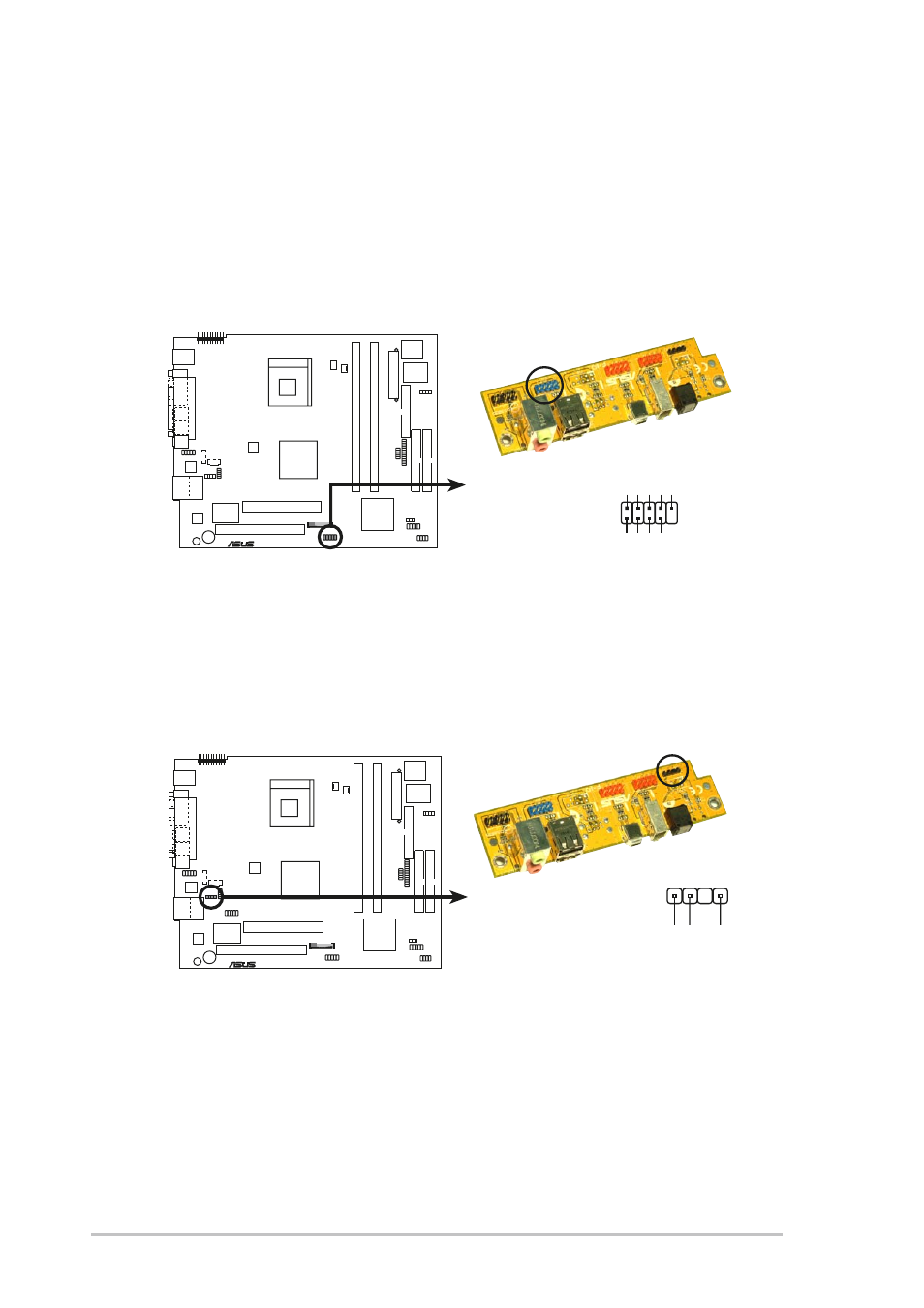
1.
Front panel USB connector (10-1 pin USB34)
The USB34 header is connected to the USB_2 connector in the front
panel I/O daughterboard.
P4R8T
®
P4R8T Digital Audio Connector
+5V
SPDIFOUT
GND
SPDIF OUT
2.
Digital audio connector (4-1 pin SPDIF_OUT)
The SPDIF_OUT is connected to the SPDIF_OUT2 connector in the
front panel I/O daughterboard to support the optical S/PDIF port.
P4R8T
®
P4R8T USB Connector
USB Power
USBP2–
USBP2+
GND
NC
USB Power
USBP3–
USBP3+
GND
1
5
6
10
USB34
See also other documents in the category Asus Computers:
- CG8565 (410 pages)
- CG8565 (246 pages)
- CS5111 (26 pages)
- CS5120 (1 page)
- ET1611PUK (38 pages)
- S2-P8H61E (80 pages)
- P2-P5945GCX (90 pages)
- P2-PH1 (80 pages)
- P1-P5945G (80 pages)
- CG8270 (362 pages)
- CG8270 (218 pages)
- CG8270 (536 pages)
- CG8270 (72 pages)
- CG8270 (76 pages)
- CG8270 (534 pages)
- P3-P5G31 (100 pages)
- P3-PH4 (80 pages)
- P2-M2A690G (80 pages)
- P2-M2A690G (8 pages)
- P4-P5N9300 (82 pages)
- P4-P5N9300 (1 page)
- P1-P5945GC (92 pages)
- P2-P5945GC (92 pages)
- P3-P5G33 (98 pages)
- T3-P5945GC (80 pages)
- T3-P5945GCX (80 pages)
- P2-M2A690G (94 pages)
- T3-PH1 (82 pages)
- T3-PH1 (80 pages)
- T5-P5G41E (76 pages)
- T5-P5G41E (82 pages)
- S1-AT5NM10E (68 pages)
- P6-P7H55E (67 pages)
- ES5000 (174 pages)
- T4-P5G43 (104 pages)
- T-P5G31 (92 pages)
- BT6130 (60 pages)
- BT6130 (54 pages)
- BT6130 (2 pages)
- CG8265 (210 pages)
- CG8265 (350 pages)
- CM1740 (330 pages)
- CM1740 (70 pages)
- CM1740 (198 pages)
- P6-M4A3000E (59 pages)