Asus AW171 User Manual
Page 42
2-22
Chapter 2: Hardware information
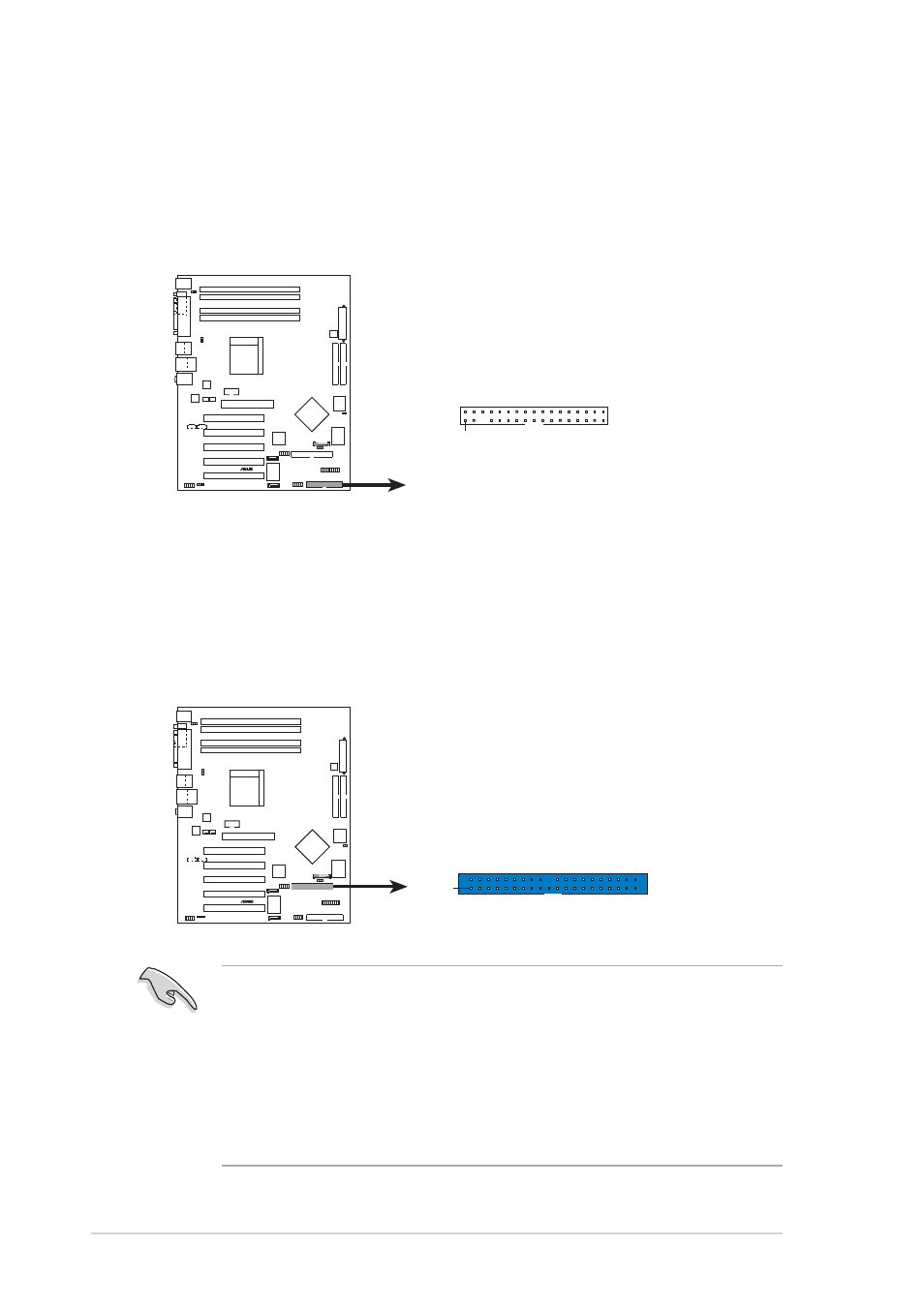
2. Floppy disk drive connector (34-1 pin FLOPPY1)
This connector supports the provided floppy drive ribbon cable. After
connecting one end to the motherboard, connect the other end to the
floppy drive. (Pin 5 is removed to prevent incorrect insertion when
using ribbon cables with pin 5 plug).
3. RAID ATA/133/100/66/33 connector (40-1 pin PRI_RAID1)
This connector support either RAID 0, RAID 1 or RAID 0 + 1
configuration with the Serial ATA connectors through the onboard
Promise
®
PDC20378 controller. You can use the RAID feature to set up
a disk array configuration and to support additional IDE devices.
Important notes on the RAID feature:
•
By default, the drive that you connect to the PRI_RAID
connector follow the ATA133/100/66/33 protocol as an
independent drive, not as a disk array.
•
The RAID/SATA controller chipset does not support ATAPI
devices such as CD-ROMs, DVD-ROMs, etc.
SK8N
®
NOTE: Orient the red markings on
the floppy ribbon cable to PIN 1.
SK8N Floppy Disk Drive Connector
FLOPPY1
PIN 1
SK8N
®
SK8N RAID Connector
NOTE: Orient the red markings
(usually zigzag) on the IDE
ribbon cable to PIN 1.
PRI_RAID1
PIN 1