2 motherboard overview, 1 motherboard layout, 2 layout contents – Asus P8H67-I User Manual
Page 13: Motherboard overview -2 1.2.1, Motherboard layout -2, Layout contents -2
ASUS P8H67-I
1-2
P8H67-
I
PCI1EX16
USB1112
USB910
AAFP
RTL
8111E
ASM
1042
ATX12V
EATXPW
R
F_PANEL
CPU_FAN CHA_FAN
Lithium Cell
CMOS Powe
r
VIA
VT1708S
EPU
IT
8756E
32Mb
BIOS
SB_PWR
CLRTC
SPDIF_OUT
17.1cm
(6.75in)
17.1cm(6.75in)
DDR3 DIMM_A1 (64bit, 240-pin module)
DDR3 DIMM_B1 (64bit, 240-pin module)
SATA6G_1
SATA6G_2
SATA3G_2
SATA3G_1
SATA3G_3
SATA3G_4
AUDIO
LAN1_USB3_12
KB_USB56
USB1_4
HDMI
SPDIF_O2
LGA1155
DVI_VG
A
Intel
®
H67
6
2
1
3
8
9
2
11
12
10
7
5
4
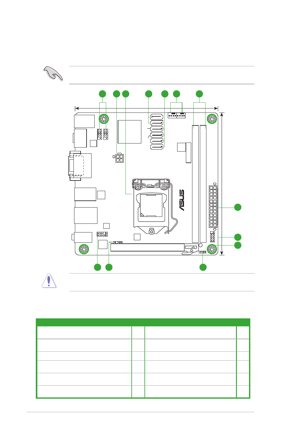
1.2.2
Layout contents
Connectors/Jumpers/Slots/LED
Page
Connectors/Jumpers/Slots/LED
Page
1. USB 2.0 connector (10-1 pin USB910,
USB1112)
1-16 7.
DDR3 U-DIMM slots
1-3
2.
ATX power connectors (24-pin EATXPWR,
4-pin ATX12V)
1-12 8.
System panel connector (10-1 pin F_PANEL) 1-15
3. Intel
®
LGA1155 CPU socket
1-3
9.
Standby power LED (SB_PWR)
1-1
4. Intel
®
H67 Serial ATA 6.0Gb/s connectors
(7-pin SATA6G_1/2 [gray])
1-14 10. Clear RTC RAM (3-pin CLRTC)
1-9
5. Intel
®
H67 Serial ATA 3.0Gb/s connectors
(7-pin SATA3G_1/2/3/4 [blue])
1-14 11. Digital audio connector (4-1 pin SPDIF_OUT) 1-13
6.
CPU and chassis fan connectors (4-pin
CPU_FAN, 4-pin CHA_FAN)
1-13 12. Front panel audio connector (10-1 pin AAFP) 1-16
Place four screws into the holes indicated by circles to secure the motherboard to the
chassis. DO NOT overtighten the screws! Doing so can damage the motherboard.
Ensure that you install the motherboard into the chassis in the correct orientation. The edge
with external ports goes to the rear part of the chassis.
1.2
Motherboard overview
1.2.1
Motherboard layout