Schéma de la carte mère, Français, Carte mère asus p4sgx-mx – Asus P4SGX-MX User Manual
Page 2: Panel1, P4sgx-mx, Super i/o, Pci slot 1, Pci slot 2 pci slot 3, Sis962l mutlol media i/0, Socket 478
2
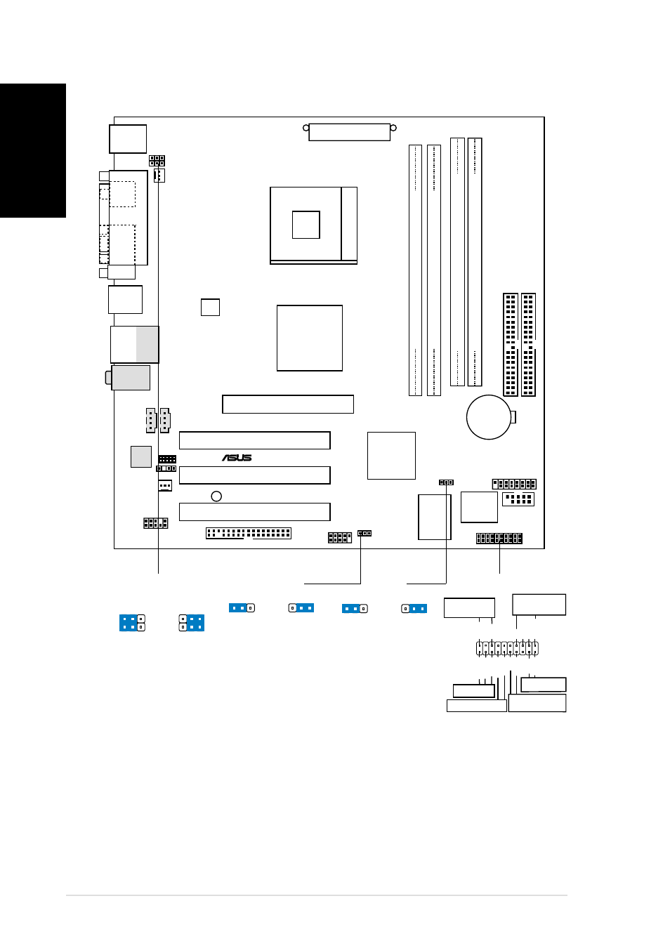
Carte mère ASUS P4SGX-MX
Français
1. Schéma de la carte mère
PANEL1
PLED
Ground
PWR
+5V
Speaker
Ground
ExtSMI#
Ground
Reset
Ground
Ground
+5VSB
IDELED+
IDELED-
Ground
SMI Lead
IDE_LED
LED alimentation
Connecteur
Haut-parleur
Bouton de reset
Commutateur
d’alimentation ATX
* Nécessite une alimentation ATX.
FLOPPY1
PANEL1
CD1
CHA_FAN1
SiS650GX
HOST/
Memory
Controller
AUX1
P4SGX-MX
®
GAME1
FP_AUDIO1
Super
I/O
2Mbit
Flash
BIOS
PCI Slot 1
SEC_IDE1
Accelerated Graphics Port
(AGP)
USBPWR_34
SiS962L
MuTLOL
Media
I/0
SPDIF_OUT1
ATX12V1
CPU_FAN1
PRI_IDE1
SB_PWR1
USBPWR_56
USB_56
COM1
Socket 478
PCI Slot 2
PCI Slot 3
PS/2KBMS
T: Mouse
B: Keyboard
P
ARALLEL
POR
T
VGA1
Below:Mic In
Center:Line Out
Top:Line In
RJ-45
Top:
USB3
USB4
Bottom:
USB20_12
ATX Power Connector
DIMM Socket 1 (64/72-bit, 168-pin module)
2 3
DIMM Socket 1 (64/72-bit, 168-pin module)
0 1
DDR DIMM2 (64/72 bit, 184-pin module)
2 3
DDR DIMM1 (64/72 bit, 184-pin module)
0 1
USBPWR_12
Audio
Codec
CLRTC1
CR2032 3V
Lithium Cell
CMOS Power
SPDIF1
MDC1
Normal
(Default)
1 2
Clear CMOS
3
2
CLRTC1
+5V
(Default)
1 2
+5VSB
3
2
USBPWR_12
USBPWR_34
+5V
(Default)
1 2
+5VSB
3
2
USBPWR_56