P5q18l ide connector, P5q18l atx power connectors, 6 chapter 4: motherboard info – Asus T4-P5P43 User Manual
Page 64: Eatxpwr, Atx12v, Pri_ide
4-6
Chapter 4: Motherboard Info
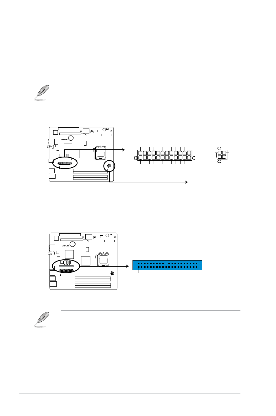
2. ATX power connectors (24-pin EATXPWR, 4-pin ATX12V)
These connectors are for the 24-pin and 4-pin power plugs from the power
supply unit. The plugs from the power supply unit are designed to fit these
connectors in only one orientation. Find the proper orientation and push down
firmly until the connectors completely fit.
Do not forget to connect the 4-pin ATX12V power plug to the ATX12V connector
on the motherboard. Otherwise, the system will not boot up.
3. IDE connector (40-1 pin PRI_IDE)
This connector is for an IDE 100/66 signal cable, a blue connector for the
primary IDE connector on the motherboard
• Pin 20 on the IDE connector is removed to match the covered hole on the
Ultra DMA cable connector. This prevents incorrect insertion when you
connect the IDE cable.
• Use the 80-conductor IDE cable for Ultra DMA 100/66 IDE devices.
P5Q18L
P5Q18L ATX power connectors
EATXPWR
PIN
1
+3 Volt
s
-12 Volt
s
GND
PSON#
GND
GND
GND
-5 Volt
s
+5 Volt
s
+5 Volt
s
+5 Volt
s
GND
+3 Volt
s
+3 Volt
s
GND
+5 Volt
s
GND
+5 Volt
s
GND
Power OK
+5V Standby
+12 Volt
s
+12 Volt
s
+3 Volt
s
ATX12V
PIN 1
+12V DC
+12V DC
GND
GND
P5Q18L
PRI_IDE
NOTE:Orient the red markings
on the IDE ribbon cable to PIN 1.
PIN1
P5Q18L IDE connector