Radio interface – QTech Data Systems DATRAN Q80 Telemetry Radio User Manual
Page 15
TECHNICAL NOTES
TECHNICAL NOTES
TECHNICAL NOTES
TECHNICAL NOTES
www.qtech.co.nz
Tel 03 3663713
The remote power ON/OFF control line turns the NMOS FET transistor Q1 on and off via transistor Q2. The power
will be ON when 12 volts is applied to the remote power ON/OFF control line and OFF when the remote power
ON/OFF control line is grounded. Jumper J1, when installed, disables the remote power ON/OFF control.
The remote power ON/OFF control line should be connected to the
‘+’
terminal of the Q22 DATRAN eXcel Module
power connector. In most other applications the remote power ON/OFF control line is left open and jumper J1 is
installed.
Radio Interface
Radio Interface
Radio Interface
Radio Interface
The embedded Maxon Radio interface on the Q80 Motherboard provides a simple and versatile half duplex
interface between the Q80 Module and
QTech
RTU modules or customer specific equipment.
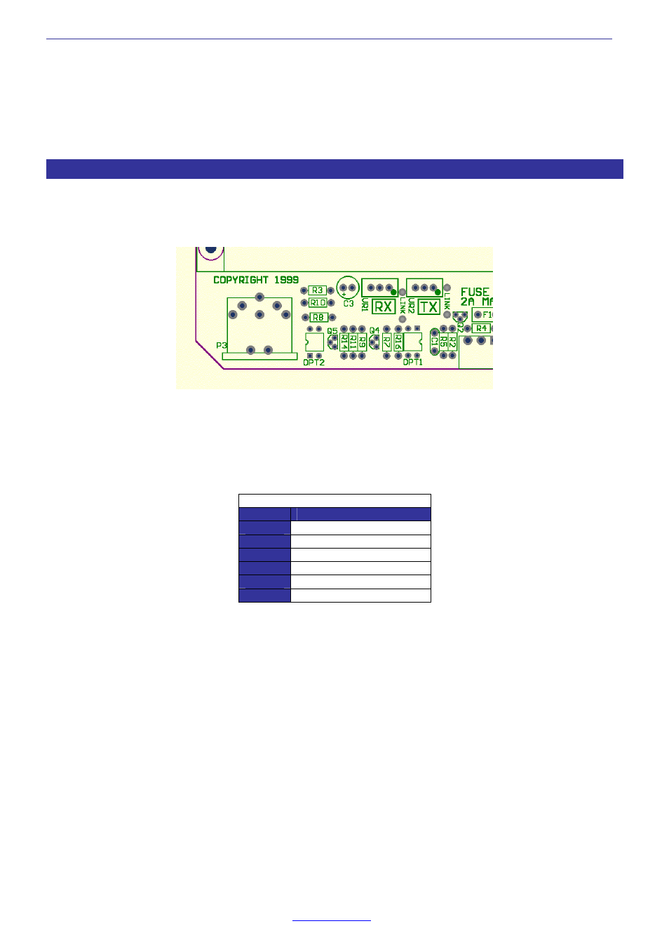
Location of Radio Interface circuitry.
The above diagram shows the location of the Q80 Module radio interface circuit located at the bottom middle left
hand side of the Q80 Motherboard as viewed with the front panel BNC RF connector to the right.
The connections to P3, the 6 way DIN Modem socket are:
Radio Patch Cord Connections
Pin No.
Function
1
Audio input/output
2
Audio input/output
3
+12 volts interface supply
4
Transmit key line
5
Ground & cable screen
6
Busy output
The diagram below shows the Radio interface circuitry.