QTech Data Systems DATRAN Q80 Telemetry Radio User Manual
Page 14
TECHNICAL NOTES
TECHNICAL NOTES
TECHNICAL NOTES
TECHNICAL NOTES
www.qtech.co.nz
Tel 03 3663713
TECHNICAL NOTES
TECHNICAL NOTES
TECHNICAL NOTES
TECHNICAL NOTES
This section describes the technical aspects of Q80 Module power supply and modem interface.
Power Supply
Power Supply
Power Supply
Power Supply
The Q80 Module is designed to operate with a DC power supply voltage of nominally 12 volt. The Q80 Module
draws approximately 80mA in Standby, 100mA on Receive and 1.2A on Transmit at 5 Watts output.
The DC power supply to the Q80 Module must be adequately smoothed and be free from noise and voltage
transients. Where the DC supply is derived from the AC mains, or batteries with an associated AC mains battery
charger these devices must comply with the required electrical regulations.
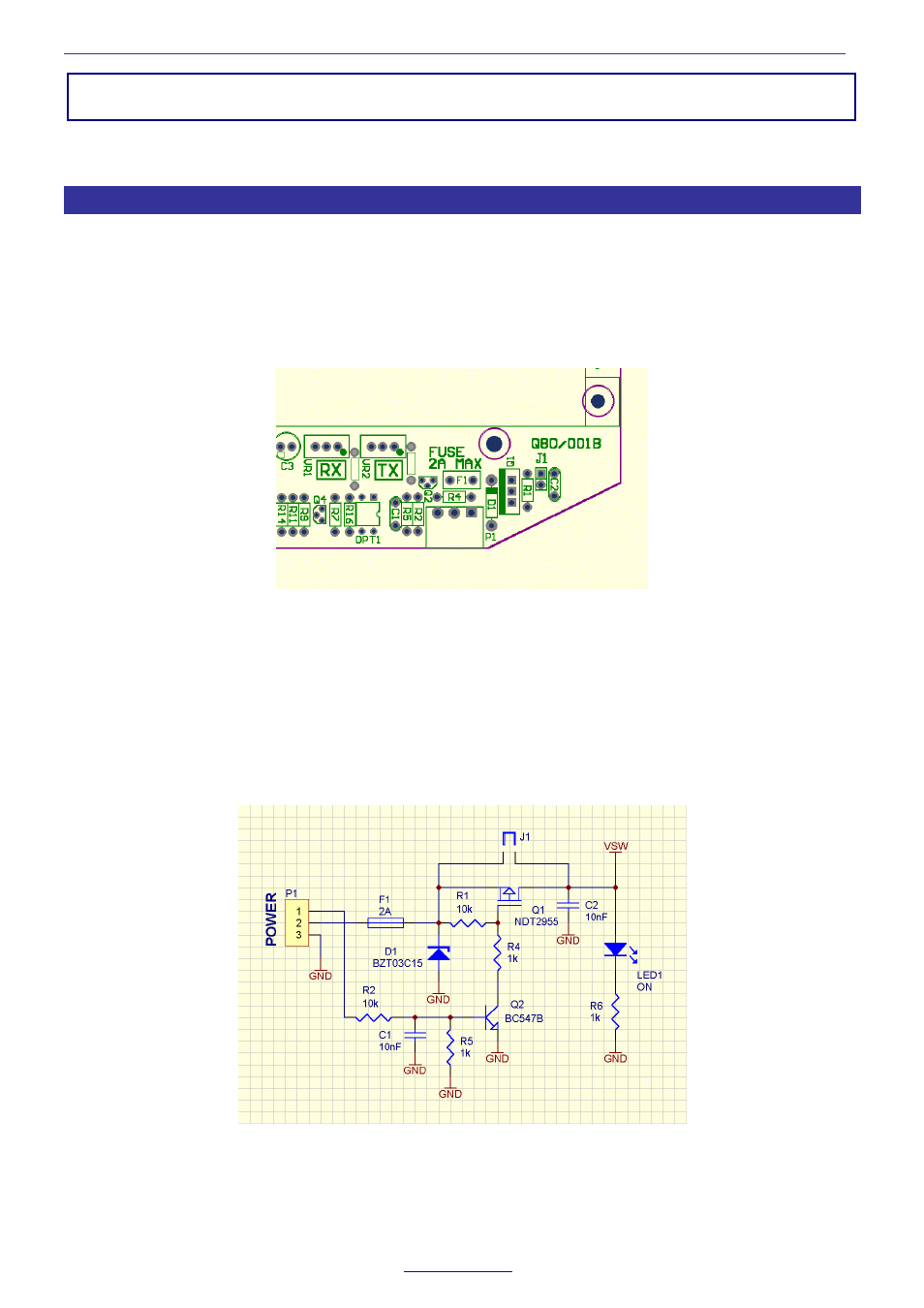
Location of Power supply circuitry.
The above diagram shows the location of the Q80 Module power supply circuit located at the bottom right hand
side of the Q80 Motherboard as view with the front panel BNC RF connector to the right. The power supply
connector P1 is a 3 way connector labelled ‘PWR’ on the bottom panel of the Q80 Module. The connections to the
power connector are:
CTL
Pin No 1 - The remote power ON/OFF control input.
+IN
Pin No 2 - The positive lead of the power supply.
G
Pin No 3 - Ground, the negative lead of the power supply.
Circuit details of Power Supply Front End.
In the above circuit diagram the 15 volt zener diode D1 and the 2 amp fuse F1 protect the Q80 module against
reverse power supply connection, over voltage and transient voltages. The fuse is a plug-in 2 amp TE5 fuse.