Procom MU 9-xp4r-... User Manual
Page 2
SPECIFICATIONS
ELECTRICAL
MODEL
MU 9-XP4R/...
ANTENNA TYPE
End-fed ½ λ mobile whip antenna
FREQUENCY
450 MHz–band covered by three
models
IMPEDANCE
Nom. 50 Ω
POLARIZATION
Vertical
GAIN
2 dB (acc. to EIA RS-329-1)
BANDWIDTH
≥ 15 MHz @ SWR ≤ 1.5
≥ 30 MHz @ SWR ≤ 2.0
SWR
≤ 1.3 @ f. res.
MAX. POWER
40 W
MECHANICAL
MATERIALS
Whip:
Black-chromed, conical stainless steel
Black-chromed brass
Mount:
Black-chromed brass
Weather- and shockproof plastics
Surface treated steel
RECOMMENDED INSTALLATION
TORQUE
Max. 3 Nm
CABLE
4 m cable terminated with FME-
connector.
Other cable lengths and connector
types on request
(see ordering designations)
COLOUR
Black
HEIGHT
Approx. 40 cm (see cutting diagram)
WEIGHT
Approx. 210 g
MOUNTING
From outside: 21 mm dia. hole
From inside: 14 mm dia. hole
ROOF THICKNESS
0.6 → 5.0 mm
INSTALLATION
This antenna is especially designed for installation on non-conducting
surfaces as e.g. glass fibre roofs, as can be found on some trucks, busses,
transport vans and trains.
The antenna is an end-fed, ½ λ-dipole concept which can be fed in such a
way that the antenna does not require a “groundplane” as required by the
standard ¼ λ, ⅝ λ or colinear mobile whips.
It is useful to note that this antenna type can be used anywhere, where the
ground-plane is poor or completely missing, as e.g.: side-mounted on a
clamp as a pager antenna on a wall, or mounted at the very edge of a
ground-plane without the loss induced by a tilted radiation pattern.
The antenna must be mounted on a horizontal surface. When cleaning the
vehicle in car-washing machines, the whip is easily dismounted using a
spanner, size 9 mm. The whip is refitted again by screwing it onto the M6
thread stud on the mount and tightening it lightly with the spanner.
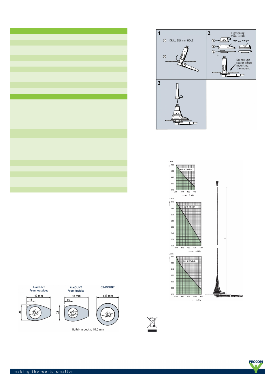
1. INSTALLATION DIMENSIONS
2. INSTALLATION STEPS (From outside)
Do not use sealer on rubber gasket or other places.
3. TUNING
The antenna should always be tuned using an SWR-indicating device. The
cutting diagrams below serve as a guide for this procedure.
PROCOM A/S reserve the right to amend specifications
without prior notice.
18/02/13