English – Pfister F-049-SYKK User Manual
Page 4
ENGLISH
ENGLISH
8
10
9
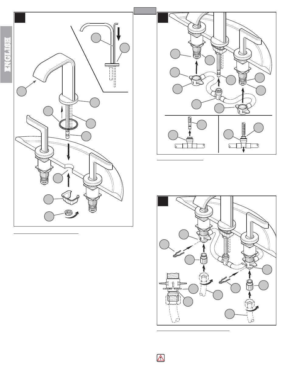
10 WATER SUPPLY CONNECTIONS
First, thread Inlet Connectors (10A) into Water Supply Lines (10B). Then, insert Inlet
Connectors (10A) into Valve Bodies (10C).
Hot water supply lines go into left inlet.
Cold water supply lines go into right inlet. (Supply lines not included). Please follow
manufacturer’s instructions when installing supply lines. Next, insert Clips (10D) into
Valve Body Holes (10E), to secure unit.
WARNING: Do not twist Inlet Connectors (10A) once installed!
9 HOSE CONNECTION
From underneath sink, push the Center Connector (9A) onto receiving Tube (9B), until
unable to push any further. Pull down on the quick connect housing (9A). If the housing
and the Inner Collet (9C) separate slightly but do not pull off receiving Tube (9B), the
connection is secure.
Slide the End Connectors (9D) with arrow (9E) pointing up onto the Valve Bodies (9F).
Push the End Connectors (9D) all the way up until completely seated. Be careful not
to damage O-Rings (9G).
8 SPOUT BODY INSTALLATION
Insert Lift Rod (8A) into hole at the back of Spout (8B). Place Plastic Seal Ring (8C)
against the bottom of Spout Body (8D). With Spout Body (8E) facing forward, carefully
install the Lift Rod (8A), and Shank (8F) through the center hole of sink (8G).
From underneath sink, secure Spout Body (8E) by placing Thrust Washer (8H) and
threading Locknut (8J) onto Shank (8F).
Caution: Do not over tighten!
4
HOT
COLD
8A
8B
8C
8D
8A
8F
8G
8H
8J
9A
9E
9D
9F
9G
9G
9F
9D
9C
9B
9C
9C
9B
10A
10B
10B
10E
10D
10A
10C
10C
10D
10D
8E