Peel -n - stick, 32 1 i iii, Danger – Factory Direct Hardware LCN 4040XP User Manual
Page 2: 180° template p.a. mounting instruction sheet, Caution
EXTERIOR
INTERIOR
8.5 lb-f
34"
54"
60"
30"
36"
42"
48"
SET TO:
48"
38"
1
3
4
5
6
6
DOOR
WIDTH
2
3
2
1
180° Template
P.A. Mounting
INSTRUCTION SHEET
5
3
4
III
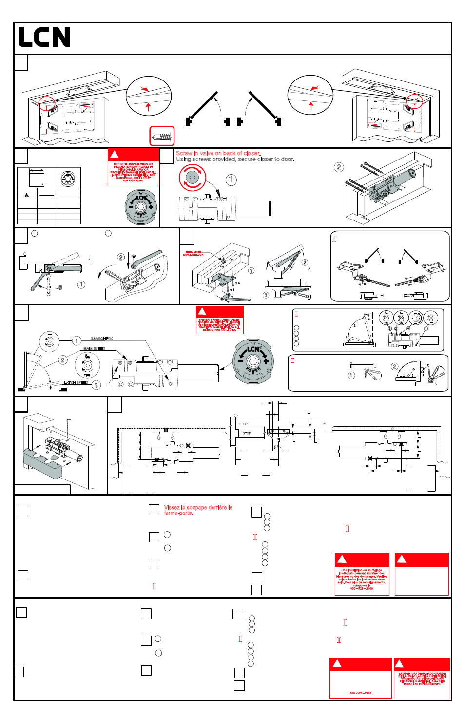
1 Pre-load closer to
30°, as shown.
I
Optional Hold-open arm. Identify direction
of hold-open nut according to mounting.
To adjust Optional
Hold-open arm:
Loosen hold open nut.
Open door to desired
position and tighten
hold open nut securely.
Attach cover with fasteners
provided.
Locate proper template. Peel template and apply so red arrows align. Center punch all hole
locations. For self reaming tapping screws (SRT) drill 1/8" pilot holes. Remove template before installing closer.
1
7
8
Dimensional Information for standard
and delay action mounting.
6
If necessary, adjust closer
2 Attach arm to closer,
with provided fastener.
Attach P.A. shoe to frame and fasten forearm to shoe
with fasteners provided. Pre-load arm and tighten screw.
2
Determine door width, adjust
spring power to match chart.
1
2
Screw in valve on back of closer.
Using screws provided, secure closer to door.
1
30°
2
1
2
3
BACKCHECK
MAIN SPEED
LATCH SPEED
IMPROPER INSTALLATION OR
REGULATION MAY RESULT IN
PERSONAL INJURY OR
PROPERTY DAMAGE. FOLLOW ALL
INSTRUCTIONS CAREFULLY. FOR
QUESTIONS, CALL LCN AT
800 - 526 - 2400
CAUTION
!
OPENING OF REGULATION VALVES
TOO FAR MAY RESULT IN LEAKAGE
OF CLOSER, PERSONAL INJURY OR
PROPERTY DAMAGE. FOLLOW ALL
INSTRUCTIONS CAREFULLY.
CAUTION
!
8
NOTE: la fermeture d'une porte ouverte à 90°
prend normalement de 5 à 7 secondes, ce
délai est réparti entre la vitesse de fermeture
et la vitesse de verrouillage.
III
Pour régler le bras de retenue
optionnelle, desserrez la vis de
retenue. Ouvrez la porte à la
position désirée et resserrez la vis.
3
2
1
I
III
Determina la anchura de la puerta. Ajusta la
fuerza del resorte según lo indicado en el gráfico.
Brazo de retención opcional. Identifíca
la dirección de la tuerca de retención
según el montaje.
NOTA: El tiempo de cerrado "Normal" de una
puerta abierta a 90° es de 5 hasta 7 segundos,
dividido igualmente entre la velocidad principal
y la velocidad de seguro.
Para ajustar el brazo de retención
opcional: Afloja la tuerca de retención.
Abra la puerta a la posición deseada
y aprieta bien la tuerca de retención.
Localiza la plantilla apropiada. Quitar la
película, alinear las flechas rojas y aplicar la
plantilla. Marca el centro de cada agujero.
Barrena agujeros pilotos de 1/8" para los
tornillos autorroscantes. Quita la plantilla
antes de instalar el cerrador.
Dimensions
3
6
2
1
4
I
Mesurez la largeur de la porte. Réglez le ressort
selon les indications du tableau.
Bras de retenue optionnelle. Identifiez
la direction du boulon de retenue selon
l'ouverture de la porte.
4041/4040XP Instructions et gabarit autocollant de 180° pour une installation "bras parallèle".
Repérez le gabarit approprié. Retirez la pellicule,
alignez les flèches rouges et appliquez. Marquez
le centre de tous les trous. Percez des trous de
guidage de 1/8" pour les vis tarauds. Retirez le
gabarit avant de poser le ferme-porte.
7
7
Datos dimensionales para
montaje estándar y de acción
retardada.
6
4041/4040XP Instrucciones Pela y Pega para plantilla 180° con montaje del brazo paralelo.
Atornilla la válvula al revés
del cerrador.
Sujeta el
cerrador a la puerta con los
tornillos ya incluidos.
1 Préchargez le ferme-porte à 30°,
comme sur l'illustration.
2 Rattachez le bras au ferme-porte
avec l'attache fournie.
5
Rattachez le sabot du b. p. au
cadre et fixez l'avant-bras sur
le sabot avec les attaches fournies.
Préchargez le bras et serrez la vis.
Vissez la soupape derrière le
ferme-porte.
Fixez le ferme-porte
sur la porte avec les attaches
fournies.
4
1 Precarga el cerrador a 30°,
tal como se muestra.
2 Coloca el brazo al cerrador
con el sujetador ya incluido.
5
Coloca el pie del brazo paralelo
a la armazón y coloca el
antebrazo con los sujetadores
ya incluidos. Prearma el brazo
y aprieta el tornillo.
®
UNA INSTALACIÓN O UN AJUSTE
INCORRECTORS PUEDEN RESULTAR
EN DAÑO PERSONAL O MATERIAL.
SIGA BIEN TODAS LAS INSTRUCCIONES.
PARA MÁS INFORMACIONES,
LLAMA A LCN AL
800 - 526 - 2400
ADVERTENCIA
!
LA APERTURA DEMASIADO GRANDE
DE LAS VÁLVULAS DE AJUSTE PUEDE
OCASIONAR UN DERRAME, DAÑO
PERSONAL O MATERIAL. SIGA BIEN
TODAS LAS INSTRUCCIONES.
ADVERTENCIA
!
DANGER
!
UNE OUVERTURE EXAGÉRÉE DES
SOUPAPES DE RÉGLAGE PEUT
ENTRAÎNER DES FUITES, DES
BLESSURES OU DES DOMMAGES.
VEUILLEZ SUIVRE LES INSTRUCTIONS
AVEC SOIN.
Une installation ou un réglage
inadéquats peuvent entraîner des
blessures ou des dommages. Veuillez
suivre toutes les instructions avec
soin. Pour plus de renseignements,
composez le
800 - 526 - 2400
DANGER
!
Patents Pending include:
Installation System
Rapidor
TM
PROPRIETARY, LCN Division, Schlage Lock Company
NOTE: A "Normal" closing time
from 90° open position is 5
to 7 seconds, evenly divided
between main speed and latch speed.
II
Optional 4041 Delay
1 - Backcheck
2 - Main Speed
3 - Latch Speed
4 - Delay Speed
1
4
3
2
3
2
1
4
For 4041 Delay 90° Mounting provides
additional delay time.
2
5/16
59 mm
2
1/4
57 mm
5
127 mm
6
1/2
165 mm
= 180°
= 90°
8
203 mm
9
1/2
241 mm
= 120°
2
5/16
59 mm
2
1/4
57 mm
5
127 mm
6
1/2
165 mm
= 180°
= 90°
8
203 mm
9
1/2
241 mm
= 120°
Coloca la tapa con los
sujetadores ya incluidos.
Left hand shown,
Right hand opposite
Sabot maingauche illustré,
sabot main droite à l'opposé.
Pie izquierdo mostrado,
Pie derecho al opuesto.
Left hand application
Application main gauche
Aplicación para mano izquierda.
Right hand application
Application main droite
Aplicación para mano derecha.
Fixez le boîtier avec
les attaches fournies.
=
63 N-m
46 ft/lbs
MAXIMUM
OPENING
TORQUE
=
63 N-m
46 ft/lbs
MAXIMUM
OPENING
TORQUE
1
25 mm
1
25 mm
25 mm
1
25 mm
1
7
7/8
200 mm
1
11/16
43 mm
1
1/16
27 mm
11/16
1
3/4
17 mm
44 mm
5/16
8 mm
= 180°
= 90°
10
254 mm
11
1/2
292 mm
= 120°
CL
1
FIFTH HOLE
SPACER BLOCK
x 4
x 1
LCN FAST Power Adjust
TM
8
LCN FAST Power Adjust
TM
for Spring Power
Adjustment
®
TM
Réglage de force LCN FAST
pour régler la force du ressort
®
TM
LCN FAST cuadrante de ajuste
para ajustar la potencia del resorte
®
* Locate closer & shoe from centerline of
pivot or swing clear hinge pin when used.
1-800-526-2400
LH
RH
SRT Screw
Para la Retención del 4041, un montaje de 90° dará un
tiempo de retención adicional.
Pour le 4041 l’installation de la Retenue 90° permet un
délai de retenue additionnel.
Reduce installation torque if using SRT
screws in wood. The use of wood screws
is recommended for wood.
Si se usan tornillos de rosca cortante en la madera, se
deberá reducir el par de apretado. Con la madera, se
recomienda utilizar tornillos para madera.
Réduisez le couple de serrage à l'installation des vis tarauds
dans le bois. Les vis à bois sont recommandées pour le bois.
© 2002 SCHLAGE LOCK Compan
y DP # 27669R7
II
Au besoin, réglez
3 - vitesse de verrouillage
4 - vitesse de retenue
4041 Action retardée optionnelle
1 - résistance d'ouverture
2 - vitesse de fermeture
1 - résistance d'ouverture
2 - vitesse de fermeture
3 - vitesse de verrouillage
II
Ajusta si es necesario.
3 - velocidad de seguro
4 - velocidad de retardo
4041 Acción retardada opcional.
1 - resistencia de apertura
2 - velocidad principal
1 - resistencia de apertura
2 - velocidad principal
3 - velocidad de seguro
4041/4040XP
PEEL
-N -
STICK
ALIGN THIS EDGE
WITH BOTTOM
SURFACE OF
(RIGHT HAND)
FRAME STOP
HINGE LINE / DOOR EDGE
ALIGNTHIS EDGE
WITH BOTT
OM
SURFACE OF
(LEFT HAND)
FRAME STOP
SCREW IN VALVE
ON BACK OF CLOSER !
REMOVE TEMPLATES BEFORE
INSTALLING CLOSER
TO DOOR
PRE-DRILL (4) - 1/8"
HOLES
+
© 2007 SCHLAGE LOCK Compan
y DP # 27669R8
For Delay closer location
refer to instruction sheet
For Delay c
loser location
refer to instruction sheet
* Locate c
loser & shoe fr
om centerline of
piv
ot or s
wing c
lear hing
e pin when used.
180° TEMPLATE
P.A. Mount
PRINCETON, IL 61356 USA
800-526-2400
®
Design Patent Number 6,317,996 B1
Rapidor Installation System P
atent Pending
TM
4041/4040XP
ALIGNTHIS EDGE
WITH BOTT
OM
SURFACE OF
(RIGHT HAND)
FRAME STOP
HINGE LINE / DOOR EDGE
ALIGN THIS EDGE
WITH BOTTOM
SURFACE OF
(LEFT HAND)
FRAME STOP
SCREW INVAL
VE
ON BACK OF CLOSER !
REMOVE
TEMPLATES BEFORE
INSTALLING CLOSER
TO DOOR
PRE-DRILL (4) -1/8"
HOLES
+
© 2007 SCHLAGE LOCK Compan
y DP # 27669R8
For Delay c
loser location
refer to instruction sheet
For Delay closer location
refer to instruction sheet
* Locate c
loser & shoe fr
om centerline of
piv
ot or s
wing c
lear hing
e pin when used.
180°TEMPLA
TE
P.A.
Mount
PRINCETON, IL 61356 USA
800-526-2400
®
Design Patent Number 6,317,996 B1
Rapidor Installation System P
atent Pending
TM
4041/4040XP