Installation procedure – Factory Direct Hardware Toto HDR110#SS Clean Dry User Manual
Page 4
Installation Procedure
To be continued on the back
・
・
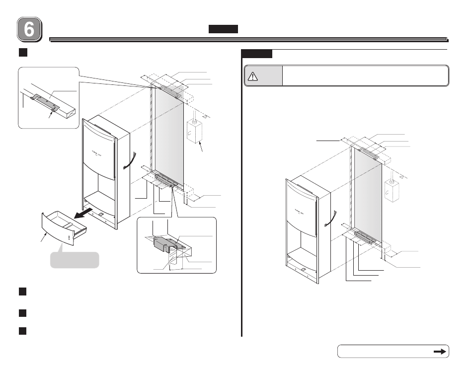
Attach the bracket firmly on the rigid wall with the three screws (
φ4.5×30
)
provided.
In the case of a tile or concrete wall, please use plastic plug anchors with
screws provided.
Mark the wall with template and install the bracket
Caution
Chassis Assy. must be installed on a rigid and even surface
Failure to do this may cause damage or personal injury when it falls.
STEP 1
STEP 1
*
Recommended mounting bracket heights from floor are as follow:
- Male/Female: 29-1/2” (750 mm)
- Children: 23-1/2” (598 mm)
- Handicapped: 21-1/2” (547 mm)
1-9/16
″
(
40mm)
Finished
wall
Finished
wall
1-9/16
″
(40mm)
3-1/8
″
(80mm)
2-3/4
″
(70mm)
2-3/4
″
(70mm)
Bracket (Bottom)
Beam/Stud
1-9/16
″ (
40mm)
Wall
Finished Wall
Remove drain tray
during installation
△
Junction box
location
Drain tray
Wall thickness needs
to be 5 to 30mm.
Wall thickness needs
to be 5 to 30mm.
Bracket
(Top)
Beam/Stud
1
Using template provided, mark the wall for locations and install
the mounting bracket.
2
Complete the electrical wiring; install the junction
box, and connect the power cord using wire nuts.
3
Mount the chassis assembly and drain tray assembly
4
Install the top cover and drain tray
1-9/16
″
(40mm)
1-9/16
″
(40mm)
3-1/8
″
(80mm)
2-3/4
″
(70mm)
2-3/4
″
(70mm)
1-3/16
″ (
30mm)
1-3/16
″ (
30mm)
2
″ (
50mm)
2
″ (
50mm)
3-9/16″ (90mm)
2-3/8″ (60mm)
2-3/8″ (60mm)
3-9/16″ (90mm)
2-3/8″ (60mm)
2-3/8″ (60mm)