Data sheet, 4nsa – Procom 4NSA User Manual
Page 3
Data Sheet
4NSA
LF Interface Module, 4-Wire
The mode of operation is set in the configuration software ICS:
- Call station operation mode: One call station is expected as subscriber
- Master operation mode:
As counterpart a 4NSA as slave is expected
- Slave operation mode:
As counterpart a 4NSA as master is
expected
- No modem operation mode:
The 4NSA only transmits LF signals
A slide-in attachment on the 4NSA as well as a special call station are necessary in
order to realize the LF monitoring function.
For this an audio signal is generated cyclically over the microphone of the call station
and sent to the 4NSA. If the transmission of the LF signal fails, then an error
message is generated.
This mode is activated by ticking the option in ICS.
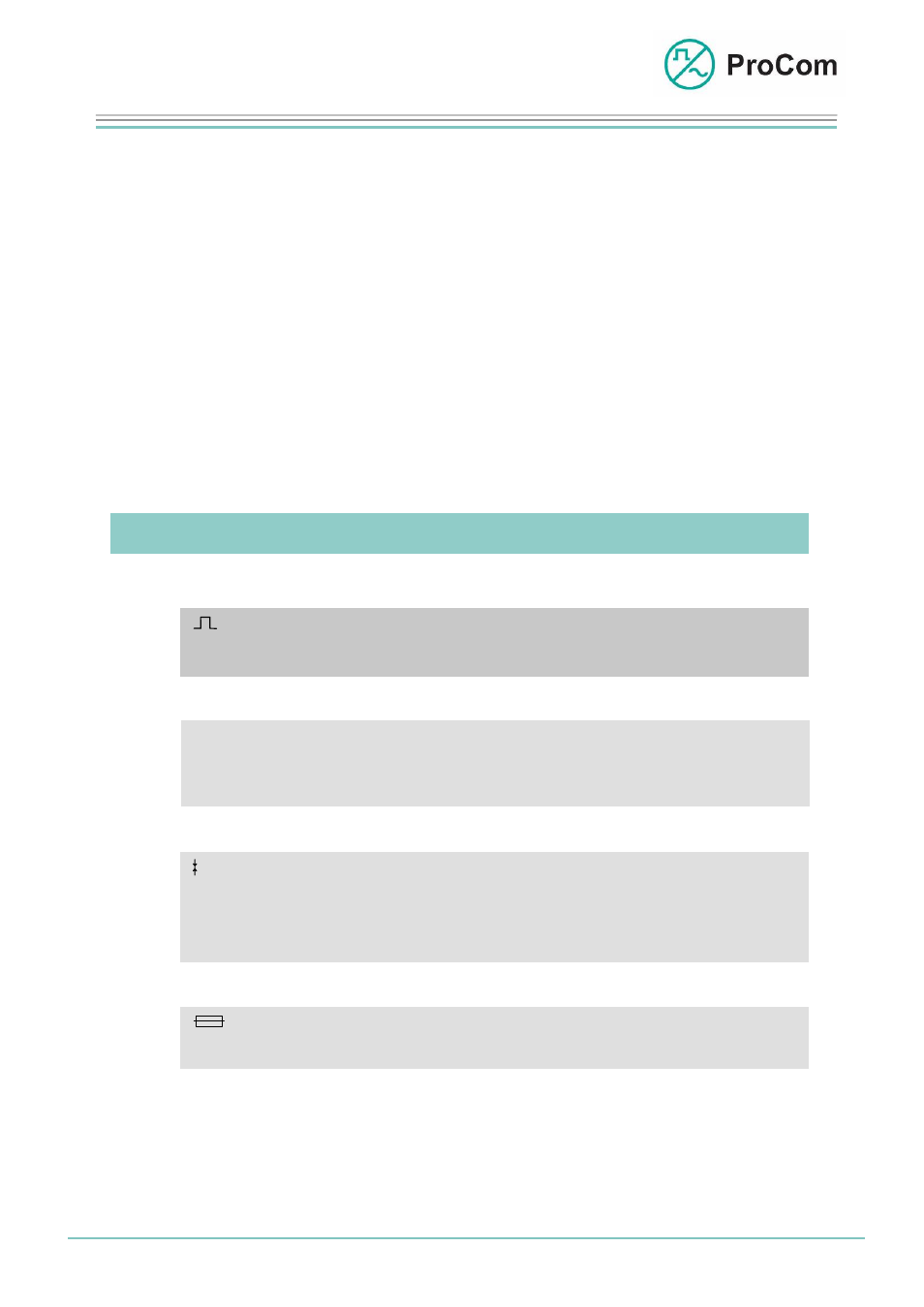
The Symbols on the Front Plate and their Meaning:
The System Blinker
Addressing from processor taking place
I/O Input/Output
BUS output works as push-push operation with the system blinker
BUS input works as push-pull operation with the system blinker
Sending/Receiving
(depending on the set)
LED lit:
4NSA sending to subscriber
LED blinking:
4NSA receiving from subscriber
LED blinking slowly: modem connection disrupted
Fuse
(depending on set)
LED off: fuse has been triggered
Date:
13.03.2009 Page:
3/4 Author:
HS
Document-No.:
DB_4NSA_ 2300_01
© 2008 ProCom, All rights and technical changes reserved