Data sheet, 4nsa, Ks bus +5v gnd -5v – Procom 4NSA User Manual
Page 2: 48v +0v
Data Sheet
4NSA
LF Interface Module, 4-Wire
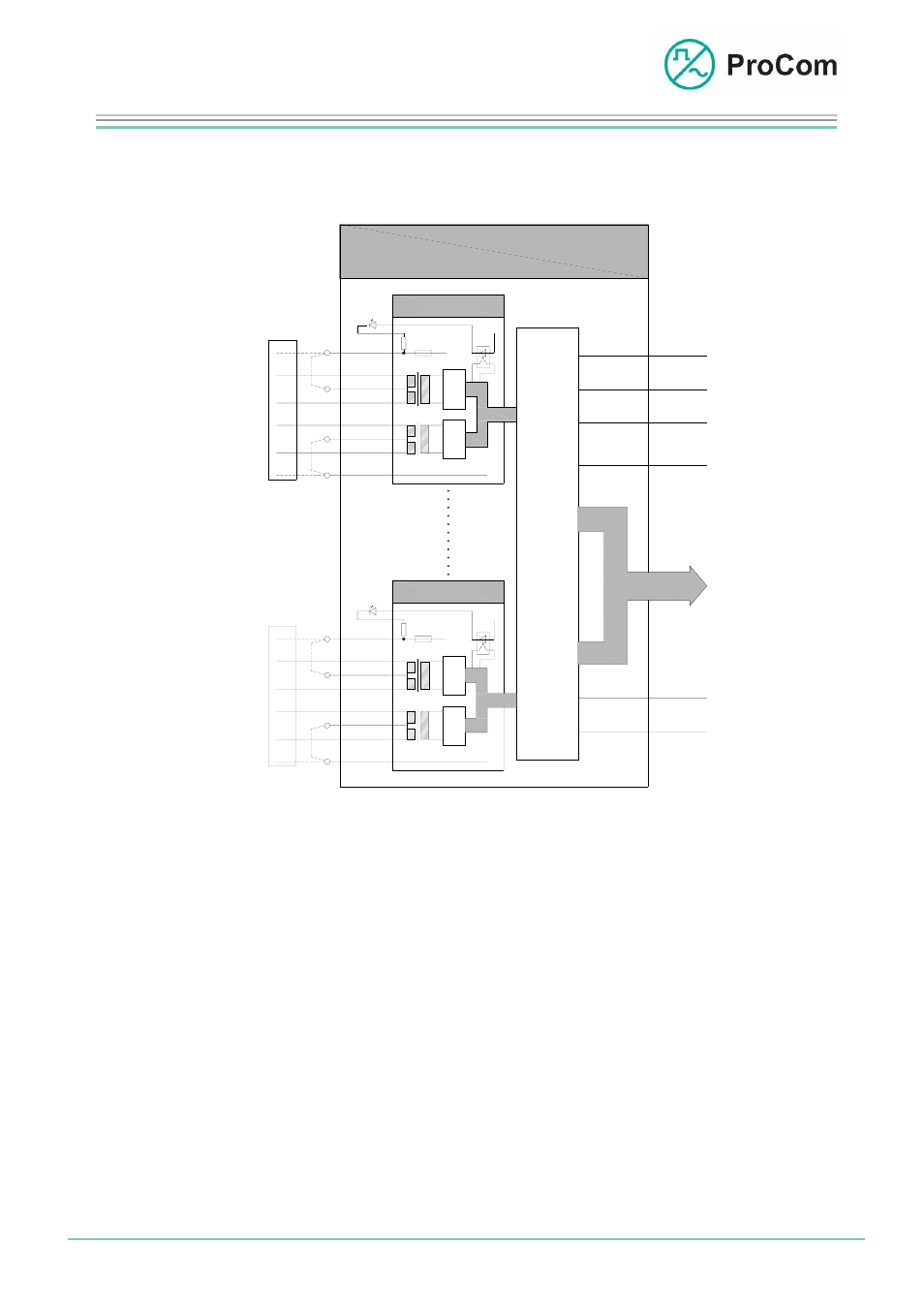
The principle functions of the 4NSA are illustrated in the following block
diagram.
KS
BUS
+5V
GND
-5V
Satz 1
Modem
-48V
+0V
4NSA
+
Lb
La
Sb
Sa
-
-48V
+
Set 1
S
p
r
e
c
h
s
t
e
l
l
e
C
a
l
l
S
t
a
t
i
o
n
Satz 4
Modem
+
Lb
La
Sb
Sa
-
-48V
+
+
S
n
g
+
S
p
r
e
c
h
s
t
e
l
l
e
t
e
u
e
r
u
C
O
N
T
R
O
L
CO
DEC
COD
E
C
Set 4
C
a
l
l
S
t
a
t
i
o
n
Block diagram 4NSA
The 4NSA has four independent sets. One call station with two wire pairs can be
connected to each set. If the 25 W booster amplifier of a call station is activated or
connected then two additional wires are necessary for voltage supply.
With a four-wire connection, jumpers on the backplane are necessary for the supply.
The voltage feed (-48 V) of each 4NSA set is fused with a 1.6 A fuse. If a fuse has
been triggered then the fuse LED switches off on the front plate and a message is
sent to the processor module CPU1.
The functionality of the LF module can be programmed per set using the
configuration software ICS. Control frames are sent bidirectionally over the modem
line (S
a
/S
b
) cyclically between the 4NSA set and a call station. If a subscriber (call
station) is absent then an error frame is sent to the CPU and the sending/receiving
LED blinks slowly.
This monitoring function can be disabled in the ICS.
The analogue voice signal from the LF line (L
a
/L
b
) is digitized on the 4NSA and
transmitted to the PCM bus.
Date:
13.03.2009 Page:
2/4 Author:
HS
Document-No.:
DB_4NSA_ 2300_01
© 2008 ProCom, All rights and technical changes reserved