Data sheet, Cpu1 – Procom CPU1 User Manual
Page 2
Data Sheet
CPU1
Processor Module
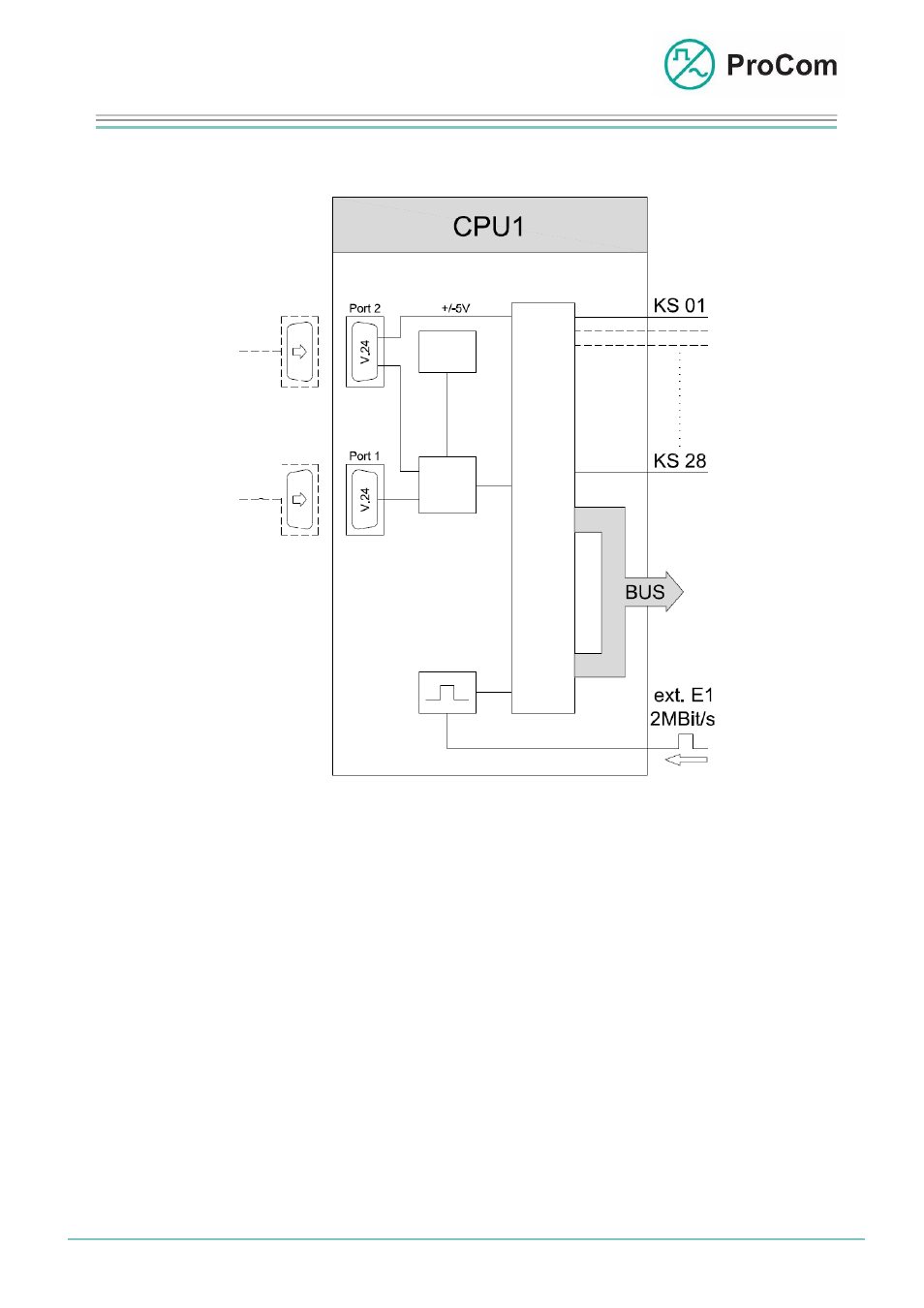
The principle functions are illustrated in the following block diagram.
DCF77
RTC
Config.
Port
CPU
Clock
Sync.
Block diagram CPU1
The processor module administers up to 28 modules of a DVS-21 system.
Communication with the modules is done through the bus system of the backplane.
- Card select (KS) 1 - 28:
Addressing of the modules in the DVS-21 system
- PCM bus: 48 PCM user channels (duplex)
A standby processor can be fitted on a special backplane variation as option. If the
active processor fails an automatic switching over to the standby CPU1 takes place.
The internal clock generator makes system clock signals available for the modules,
the PCM bus and the external interfaces.
It is possible to use an external 2 MBit/s, HDB3 signal (T2) or a 2 MHz clock signal
(T3) for clock extraction. A clock signal thus generated is available to all systems
belonging to a DVS-21 group.
The CPU1 works with the operating system “DVS-xx”. 2 firmware versions can be
stored and arbitrarily activated.
Date:
13.03.2009 Page:
2/4 Author:
HS
Document-No.:
DB_CPU1_2200_01
© 2008 ProCom, All rights and technical changes reserved