Data sheet, 4ios, Set 1 set 4 – Procom 4IOS User Manual
Page 3
Data Sheet
4IOS
Multifunction I/O Module
tivated; this means that an appropriate signal will be outputted when
an error occurs.
3. In PA and intercom systems the function e.g. “Alarm input” [Alar-
meingang]
(also binary coded)
These are configured through available programmes in the firmware ICS or speci-
fied modes of operation.
Function Description:
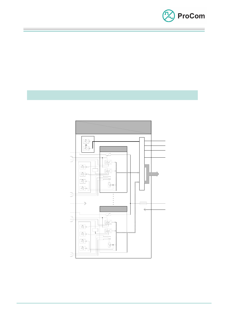
The principle functions are illustrated in the following block diagram.
4IOS
-48V
+0V
S
t
e
u
e
r
u
n
g
KS
+5V
GND
-5V
BUS
P
C
M
Satz 1
Satz 4
I
I/
O
Al
I
I/
O
Al
I/O
-48V
-OK
OK
OK'
-48V
-OK
OK
OK'
ak
mk
rk
ak
mk
rk
0V
0V
0V
U>12V
t>x
U>12V
t>x
C
O
N
T
R
O
L
Set 1
Set 4
Block diagram 4IOS
The 4IOS consists essentially of a control unit and the 4 independent sets.
Each set is equipped with a relay and 2 opto-couplers.
The relay makes available a floating switch contact.
Date: 13.03.2009
Page:
3/8 Author:
HS
Document-No.:
DB_4IOS_2804_01
© 2008 ProCom, All rights and technical changes reserved
- DSS1 (9 pages)
- WPS-04 (5 pages)
- V100 (5 pages)
- WPS-08 (5 pages)
- LCPU (5 pages)
- WPS-01 (7 pages)
- GG1_GG2_GGS_EG1_EG3 (5 pages)
- PMM-01 (9 pages)
- 4LSL (7 pages)
- DICORA S15 (2 pages)
- IP, ISDN, E1 Industrial Application (2 pages)
- CPU1 (4 pages)
- MI4M (5 pages)
- WPS-08_2 (5 pages)
- 4NSA (4 pages)
- Telco - DVS-21 (2 pages)
- WPS-04 Exx (5 pages)
- 24LI (4 pages)
- SV01-PL (3 pages)
- VoIP - LCPU (2 pages)
- 4 DAV (5 pages)
- SV01 (4 pages)
- NSA-PL (4 pages)
- DTA-LAN (8 pages)
- S0 Attachment (10 pages)
- DTA-012_030_048_066_084_114 (6 pages)
- 4NPA (5 pages)
- DTA-048_066_084 (5 pages)
- E1 Attachment (7 pages)
- USE2.OB (6 pages)
- TG01 (4 pages)
- AWC-06 (5 pages)
- WPS-04_2 (5 pages)
- Smart DVS-21 (2 pages)
- DTA-F (6 pages)
- PMS-01 DL (2 pages)
- PRO-phy150-4di-... (1 page)
- G-CXL 225-450C (2 pages)
- PRO-DIPX 225-330-n-xs (2 pages)
- PRO-cav150-3 (1 page)
- PRO-47-001 (1 page)
- MU 4-zg-... (2 pages)
- G-cxl-900-1800-1900-umts-lw (2 pages)
- BCL 1-KA (2 pages)