Data sheet, Dss1 – Procom DSS1 User Manual
Page 7
Data Sheet
DSS1
Digital Speech Memory Module
The Front Plate Symbols and their Meaning:
The System Blinker
Addressing from processor taking place
I/O Input/Output
BUS output works as push-push operation with the system
blinker
BUS
input works as push-pull operation with the system blinker
01 - 03 Status Display Set 1
13 - 15
04 - 06 Status Display Set 2
16 - 18
07 - 09 Status Display Set 3
19 - 21
10 - 12 Status Display Set 4
22 - 24
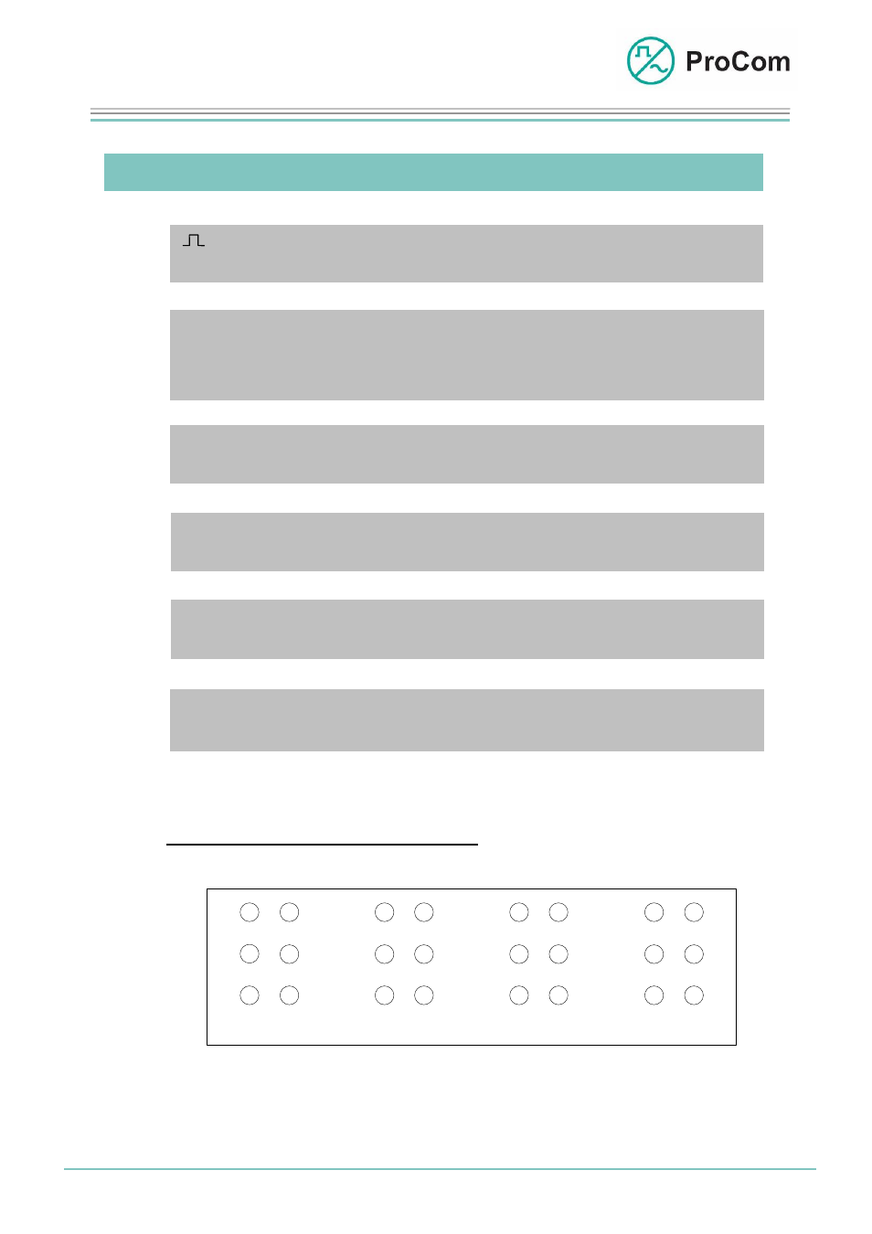
LED Displays (depending on the set):
Set 1
1
2
3
13
14
15
4
5
6
16
17
18
Set 2
7
8
9
19
20
21
Set 3
10
11
12
22
23
24
Set 4
Set-related arrangement of the front plate LEDs
Date: 13.03.2009
Page:
7/9 Author:
HS
Document-No.:
DB_DSS1_2600_01
© 2008 ProCom, All rights and technical changes reserved
- 4IOS (8 pages)
- WPS-04 (5 pages)
- V100 (5 pages)
- WPS-08 (5 pages)
- LCPU (5 pages)
- WPS-01 (7 pages)
- GG1_GG2_GGS_EG1_EG3 (5 pages)
- PMM-01 (9 pages)
- 4LSL (7 pages)
- DICORA S15 (2 pages)
- IP, ISDN, E1 Industrial Application (2 pages)
- CPU1 (4 pages)
- MI4M (5 pages)
- WPS-08_2 (5 pages)
- 4NSA (4 pages)
- Telco - DVS-21 (2 pages)
- WPS-04 Exx (5 pages)
- 24LI (4 pages)
- SV01-PL (3 pages)
- VoIP - LCPU (2 pages)
- 4 DAV (5 pages)
- SV01 (4 pages)
- NSA-PL (4 pages)
- DTA-LAN (8 pages)
- S0 Attachment (10 pages)
- DTA-012_030_048_066_084_114 (6 pages)
- 4NPA (5 pages)
- DTA-048_066_084 (5 pages)
- E1 Attachment (7 pages)
- USE2.OB (6 pages)
- TG01 (4 pages)
- AWC-06 (5 pages)
- WPS-04_2 (5 pages)
- Smart DVS-21 (2 pages)
- DTA-F (6 pages)
- PMS-01 DL (2 pages)
- PRO-phy150-4di-... (1 page)
- G-CXL 225-450C (2 pages)
- PRO-DIPX 225-330-n-xs (2 pages)
- PRO-cav150-3 (1 page)
- PRO-47-001 (1 page)
- MU 4-zg-... (2 pages)
- G-cxl-900-1800-1900-umts-lw (2 pages)
- BCL 1-KA (2 pages)