Data sheet, Dss1, Playback – Procom DSS1 User Manual
Page 3
Data Sheet
DSS1
Digital Speech Memory Module
Function Description:
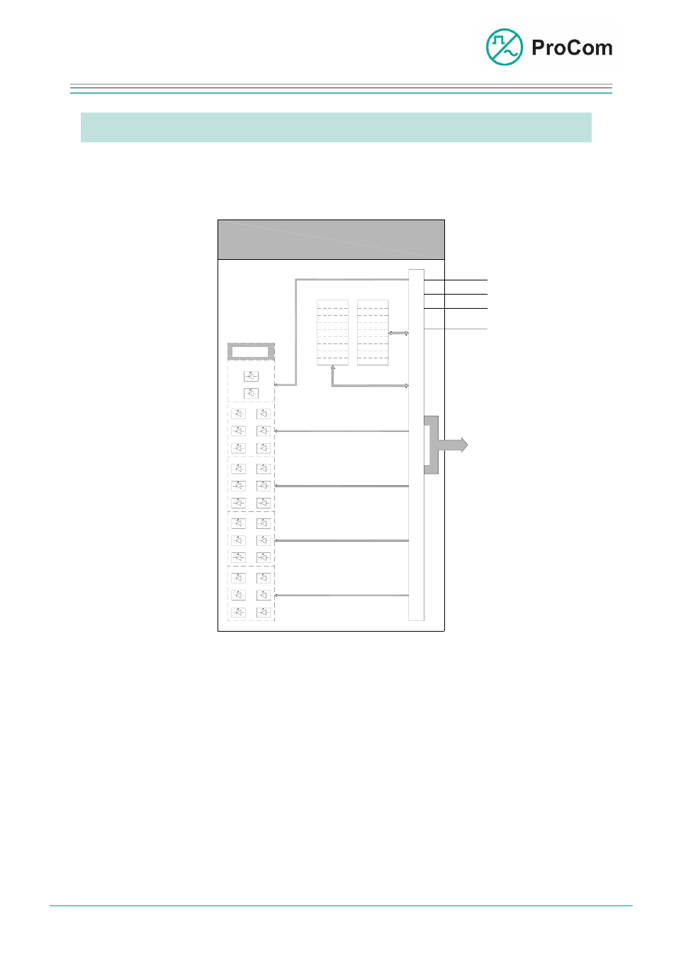
The principle functions are illustrated in the following block diagram.
Anzeige
LED 01
LED 02
I/O
System-
blinker
S
t
e
u
e
r
u
n
g
KS
+5V
GND
-5V
BUS
P
C
M
LED 13
LED 14
LED 03
LED 15
LED 12
LED 24
LED 04
LED 16
LED 05
LED 17
LED 06
LED 18
LED 07
LED 19
LED 08
LED 20
LED 09
LED 21
LED 10
LED 22
LED 11
LED 23
FLASH
RAM
Bank 1
Bank 2
Bank 3
Bank 4
Bank 5
Bank 6
Bank 7
Bank 8
Bank 1
Bank 2
Bank 3
Bank 4
Bank 5
Bank 6
Bank 7
Bank 8
S
a
t
z
1
S
a
t
z
2
S
a
t
z
3
S
a
t
z
4
DSS1
C
O
N
T
R
O
L
Indication
S
e
t
1
S
e
t
2
S
e
t
3
S
e
t
4
Block diagram DSS1
The DSS1 consists essentially of a control unit and the RAM and the flash chips.
The module communicates over the PCM bus on 8 of 64 traffic channels (VKW).
Here the following allocation applies:
• Set 1 low frequency: Recording VKW 26 and
playback
VKW 22
• Set 2 low frequency: Recording VKW 27 and playback VKW 23
• Set 3 low frequency: Recording VKW 28 and playback VKW 24
• Set 4 low frequency: Recording VKW 29 and playback VKW 25
Date: 13.03.2009
Page:
3/9 Author:
HS
Document-No.:
DB_DSS1_2600_01
© 2008 ProCom, All rights and technical changes reserved