Table of contents 1 welcome, 2 how to use this manual, Cts 4200 – Crown Audio CTs Series (Multi-Channel) User Manual
Page 3: Cts 8200
Operation Manual
CTs Power Amplifiers
page 4
page 5
CTs Power Amplifiers
Operation Manual
Important Safety Instructions ....................................................... 2
Declaration of Conformity ............................................................ 3
1 Welcome ..................................................... 5
1.1 Features ............................................................................ 5
2 How to Use This Manual ................................... 5
3 Setup ......................................................... 6
3.1 Unpack Your Amplifier ...................................................... 6
3.2 Install Your Amplifier ......................................................... 6
3.3 Ensure Proper Cooling ...................................................... 6
3.4 Choose Input Wire and Connectors ................................... 7
3.5 Choose Output Wire and Connectors ................................ 7
3.6 Wire Your System .............................................................. 8
3.6.1 Dual 8/4 Mode .......................................................... 8
3.6.2 Dual 70V Mode ......................................................... 8
3.6.3 Bridge-Mono 16/8 Mode .......................................... 9
3.6.4 Bridge-Mono 100V Mode ......................................... 9
3.7 Connect to AC Mains ........................................................ 10
3.8 Startup Procedure ............................................................. 10
4 Operation .................................................... 11
4.1 Precautions ....................................................................... 11
4.2 Front Panel Controls and Indicators .................................. 12
4.3 Back Panel Controls and Connectors ................................ 13
5 Advanced Features and Options .......................... 14
5.1 Protection Systems ........................................................... 14
5.1.1 Thermal Level Control (TLC) ..................................... 14
5.1.2 Fault .......................................................................... 14
5.1.3 Fault Isolation Topology (FIT) .................................... 14
5.1.4 35-Hz High-Pass Filter .............................................. 14
5.1.5 AC Under-/Over-Voltage Protection ........................... 14
5.1.6 Power Fuse ............................................................... 14
5.1.7 Inrush Limiting .......................................................... 14
5.1.8 Variable-speed Fans .................................................. 14
5.2 Advanced Features ............................................................ 14
5.2.1Switching Power Supply ............................................ 14
5.2.2 Mode Switch ............................................................. 14
5.2.3 Bridge Mode Indicator ............................................... 14
5.2.4 Channel Level Control ............................................... 15
5.3 Options ............................................................................. 16
5.3.1 Control Modules ....................................................... 16
5.3.2 Input Sensitivity ........................................................ 16
6 Troubleshooting ............................................ 17
7 Specifications .............................................. 19
8 AC Power Draw and Thermal Dissipation ............... 23
9 Service ....................................................... 25
9.1. International and Canada Service ..................................... 25
9.2 US Service ........................................................................ 25
9.2.1 Service at a US Service Center ................................... 25
9.2.2 Factory Service ......................................................... 25
9.2.3 Factory Service Shipping Instructions ........................ 25
9.2.4 Packing Instructions .................................................. 25
9.2.5 Estimate Approval ...................................................... 25
9.2.6 Payment of Non-Warranty Repairs.............................. 25
10 Warranty ................................................... 27
Product Registration Form ............................................................ 29
Factory Service Information Form ................................................ 31
Table of Contents
1 Welcome
Building on the foundation of the Com-Tech
®
Series, Crown’s CTs Series offers new flexibility
and value for installed sound applications. The
Com-Tech Series were the first to offer
inde pendent selection of high- and low-
impedance operation for a specific channel, and
CTs Series amplifiers continue that tradition,
with power levels and features carefully chosen
to perfectly integrate into fixed install design
requirements.
Modern power amplifiers are sophisticated
pieces of engineering capable of producing
extremely high power levels. They must be
treated with respect and correctly installed if
they are to provide the many years of reliable
service for which they were designed.
In addition, CTs Series amplifiers include a
number of features which require some
expla nation before they can be used to their
maxi mum advantage.
Please take the time to study this manual so that
you can obtain the best possible service from
your amplifier.
1.1 Features
• New Crown
®
Switching Power Supply for
reduced weight.
• High power-density, with eight channels in
a 3U chassis and four channels in a 2U
chassis.
• Selectable constant-voltage (70V/100V) or
low-impedance (8/4 ohm) operation for
each channel pair.
• FIT (Fault Isolation Topology) circuitry
isolates faults within affected channels.
• 35 Hz High-Pass Filter (70 Hz in CTs 4200)
is automatically inserted when the channel
pair is set for constant-voltage operation.
(corner frequency may be changed as a
service option).
• Accepts VC-MC accessory module that
tailors the amplifier for remote VCA level
control.
• Comprehensive array of indicators
includ ing Power and Data, along with
Bridge, Ready, Signal, Clip, Thermal and
Fault for each channel, provide accurate
diagnos tics.
• Blue Power Indicator flashes if the
ampli fier shuts off due to an under-/over-
voltage condition on the AC mains.
• Advanced protection circuitry guards
against: shorted outputs, open circuits,
DC, mismatched loads, general
overheat ing, under-/over-voltage, high-
frequency overloads and internal faults.
• Proven Crown AB+B Multi-Mode
®
output
topology.
• Continuously-variable-speed fans
opti mize cooling efficiency.
• Three Year, No-Fault, Fully-Transferable
Warranty completely protects your
invest ment and guarantees its
specifications.
2 How to Use This
Manual
This manual provides you with the necessary
information to safely and correctly setup and
operate your amplifier. It does not cover every
aspect of installation, setup or operation that
might occur under every condition. For
addi tional information, please consult Crown’s
Amplifier Application Guide (available online at
www.crownaudio.com), Crown Tech Support,
your system installer or retailer.
We strongly recommend you read all
instruc tions, warnings and cautions contained
in this manual. Also, for your protection, please
send in your warranty registration card today, or
reg ister online at www.crownaudio.com. And
save your bill of sale—it’s your official proof of
pur chase.
4-ohm (per ch.)
8-ohm (per ch.)
70V (per ch.)
1 kHz
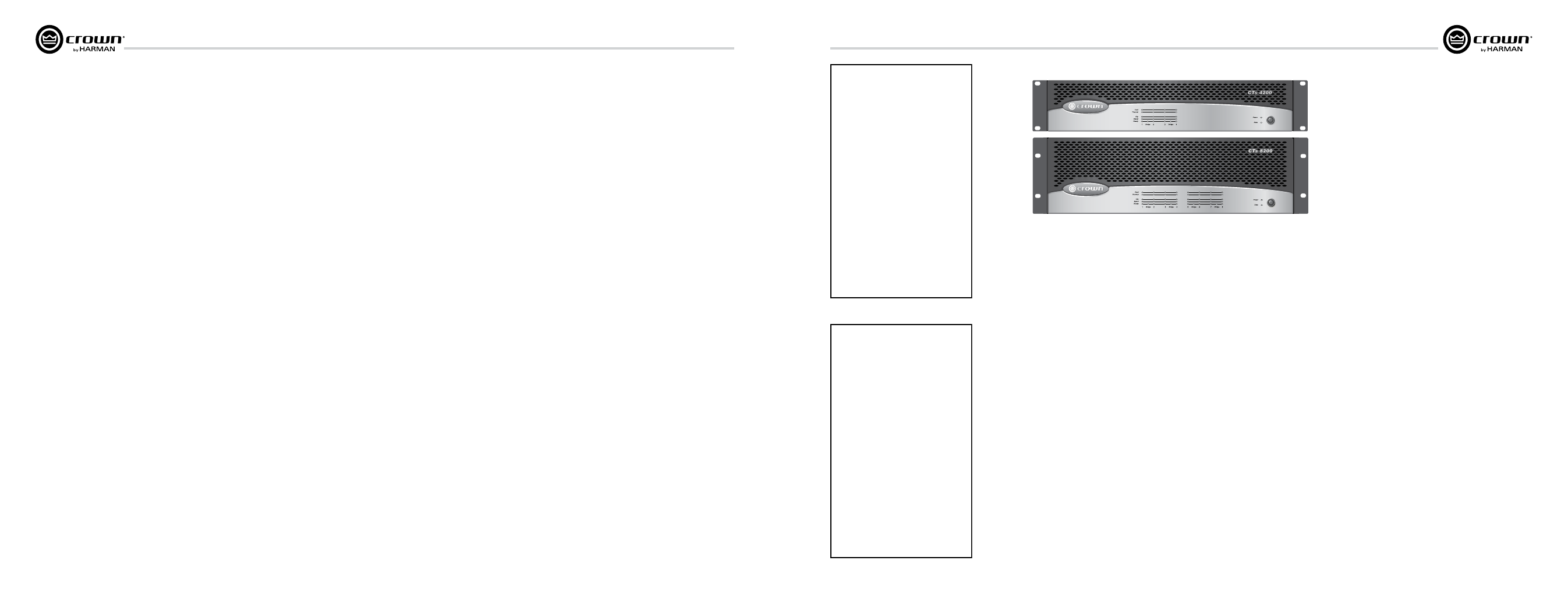
CTs 4200
20 Hz–20 kHz
Dual
4 Channels Driven
260W
180W
220W
215W
190W
220W
*
*
4-ohm (per ch.)
8-ohm (per ch.)
70V (per ch.)
1 kHz
20 Hz–20 kHz
1 Channel Driven
270W
220W
250W
225W
210W
245W
8-ohm (per ch. pair)
16-ohm (per ch. pair)
100V (per ch. pair)
1 kHz
20 Hz–20 kHz
Bridge-Mono
2 Channel-Pairs Driven
520W
400W
220W
430W
380W
220W
*
*
8-ohm (per ch. pair)
16-ohm (per ch. pair)
100V (per ch. pair)
1 kHz
20 Hz–20 kHz
1 Channel-Pair Driven
560W
440W
250W
450W
420W
245W
Maximum Average Power
in watts with 0.1% THD.
* Constant Voltage full bandwidth power ratings support
100Hz - 20kHz due to automatic High-Pass Filters.
4-ohm (per ch.)
8-ohm (per ch.)
70V (per ch.)
1 kHz
CTs 8200
20 Hz–20 kHz
Dual
8 Channels Driven
200W
160W
200W
175W
155W
185W
*
*
4-ohm (per ch.)
8-ohm (per ch.)
70V (per ch.)
1 kHz
20 Hz–20 kHz
1 Channel Driven
270W
220W
250W
230W
220W
230W
8-ohm (per ch. pair)
16-ohm (per ch. pair)
100V (per ch. pair)
1 kHz
20 Hz–20 kHz
Bridge-Mono
4 Channel-Pairs Driven
400W
320W
200W
350W
310W
185W
*
*
8-ohm (per ch. pair)
16-ohm (per ch. pair)
100V (per ch. pair)
1 kHz
20 Hz–20 kHz
1 Channel-Pair Driven
540W
440W
250W
460W
440W
230W
Maximum Average Power
in watts with 0.1% THD.
* Constant Voltage full bandwidth power ratings support
100Hz - 20kHz due to automatic High-Pass Filters.