3 setup – Crown Audio Macro-Tech MA-2402 User Manual
Page 9
page 9
MA 2402 Power Amplifier
Operation Manual
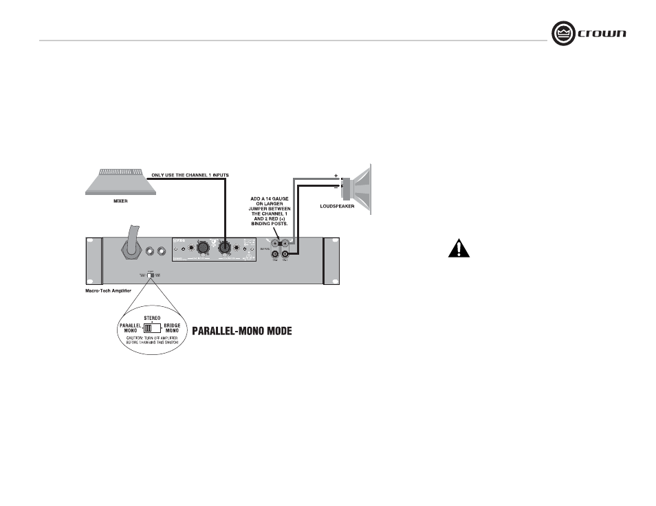
3.6.3 Parallel-Mono Mode
See Figure 3.8. Set the back panel
stereo/mono switch to Parallel-Mono.
INPUTS: Connect input wiring to Channel 1
only.
OUTPUTS: Add a 14 gauge (or larger) jumper
between the red(+) Channel 1 and Channel 2
binding posts. Connect the speaker positive (+)
lead to the Channel 1 red (+) terminal. Connect
the speaker negative (-) lead to the Channel 1
black (-) terminal.
Crown provides a reference of wiring pin assign-
ments for commonly used connector types in the
Crown Amplifier Application Guide.
NOTE: Use only the Channel 1 level
control.
CAUTION: Parallel-Mono wiring requires
installation of a jumper wire. Do not
switch to Stereo or Bridge-Mono mode
until this output jumper wire is removed.
NOTE: The Channel 2 IOC indicator will
remain lit when operating in
Parallel-Mono mode.
Figure 3.8
Parallel-Mono
Wiring
3 Setup
- MT-2400 (1 page)
- XTi 4000 (44 pages)
- 402and 602 (28 pages)
- DSi 4000 (1 page)
- S Series (28 pages)
- CTs 4200 USP/CN (2 pages)
- CH3 (2 pages)
- MA-5000i (52 pages)
- Commercial Audio Series (180MA-280MA-1160MA) (24 pages)
- Pulse 21100 (22 pages)
- Pulse 2X1100 (1 page)
- K2 (2 pages)
- XLS-602 E (1 page)
- Macro-Tech 602 (36 pages)
- I-TECH 8000 (2 pages)
- 660A (1 page)
- 5000i (1 page)
- MT 600 (1 page)
- 28M (1 page)
- PT 2.1 (2 pages)
- CTs 8200 USP/CN (2 pages)
- SR-II (1 page)
- CTs 2000 (1 page)
- 4300 (1 page)
- IQ-PIP USP3/CN (2 pages)
- 180A (1 page)
- XLS 402 (40 pages)
- 9000i (1 page)
- I (1 page)
- CL2 (1 page)
- MA-2402 (36 pages)
- CROWN K Series (20 pages)
- M Series (28 pages)
- CE 2000 (28 pages)
- Power Tech x.1 Series (24 pages)
- XTi 1000 (2 pages)
- XLS-802 (1 page)
- D-45 (24 pages)
- Xs1200 (28 pages)
- MA-24X6 (32 pages)
- I-T4000 (1 page)
- CTs 600 (32 pages)
- 12000i (2 pages)
- CDi 4000 (1 page)
- MA-3600VZ (28 pages)