2 installation, 1 stereo, 2 mono – Crown Audio CSL Series User Manual
Page 6
CSL Series Power Amplifiers
Page 6
2 Installation
Always remove power from the unit and turn the level
controls off when making connections. This reduces the
chance of loudspeaker damage from loud blasts.
Follow the guidelines listed next as well as the steps
required for the specific mode of operation:
1. Install the amplifier in a standard 19 inch (48.3 cm) rack
or place it on a stable surface. The mounting dimensions
are 19 inches (48.3 cm) wide, 3.5 inches (8.9 cm) tall
and 16 inches (40.6 cm) deep behind the mounting sur-
face.
IMPORTANT! Allow for adequate ventilation.
able with the
MT-XLR accessory. See Section 5.)
4. An appropriate AC cord and plug are provided. Use an
isolated wall outlet with the correct voltage and ad-
equate current. Voltages more than 10% over the
amplifier’s rated voltage may damage the ±15 volt regu-
Fig. 2.2 CSL Input Wiring
lator, filter capacitors and output transistors.
2.1 Stereo
1. Turn the level controls down (fully counterclockwise) and
turn off the amplifier.
2. Set the back panel stereo/mono switch to Stereo.
3. If present, remove the Parallel-Mono jumper.
4. Connect the input and output cables as shown in the first
example in Figure 2.3.
5. Turn on the amplifier and adjust the level for each chan-
nel with the back panel level controls.
CAUTION: In Stereo mode, never parallel the two
outputs by directly tying them together, and never
parallel them with the output of another amplifier.
2.2 Mono
The monaural operating modes provide twice the
power to one channel as the Stereo mode. In Bridge-
Mono mode, the outputs are wired in series for twice
the output voltage. In Parallel-Mono mode, the outputs
are paralleled for twice the current capacity.
Bridge-Mono mode is provided for loads with an im-
pedance greater than 4 ohms. Parallel-Mono mode
should be used with loads of 4 ohms or less.
B R I D G E - M O N O
1. Turn the level controls down (fully counterclockwise) and
turn off the amplifier.
2. Set the back panel stereo/mono switch to Bridge-Mono.
3. If present, remove the Parallel-Mono jumper.
4. Connect the input and output cables as shown in the
second example in Figure 2.3.
Use the Ch.1 input only.
5. Make sure the load is balanced (neither side shorted to
ground) and do not use the black (–) banana jacks.
6. Turn on the amplifier and adjust the level.
Use the Ch.1
level control only.
P A R A L L E L - M O N O
1. Turn down the level controls (fully counterclockwise) and
turn off the amplifier.
2. Set the back panel stereo/mono switch to Parallel-Mono.
3. Install a solid jumper (at least 14 gauge) across the out-
put between the two red (+) banana jacks.
4. Connect the input and output cables as shown in the
third example in Figure 2.3.
Use the Ch.1 input only.
5. Turn on the amplifier and adjust the level.
Use the Ch.1
level control only.
CAUTION: When wired for Parallel-Mono mode, do
not attempt to operate the amplifier in Stereo or
Bridge-Mono mode until the output jumper is re-
moved. Failure to do so will result in inefficient op-
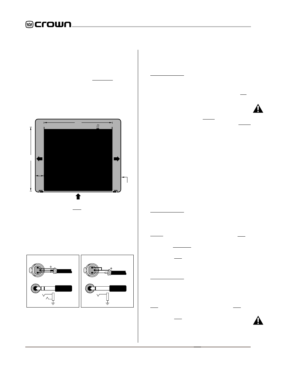
AIR
FLOW
AIR FLOW
AMPLIFIER
(TOP VIEW)
RACK
CABINET
16 in
40.6 cm
2 in
MIN.
17 in
43.2 cm
AIR
FLOW
IMPORTANT: Be sure the back of
the amplifier is supported.
Fig. 2.1 Do NOT Block Air Flow
2. Use high-quality loudspeaker cables to connect the load
to the amplifier’s output jacks. Do not use shielded
cable. Banana plugs are recommended for this connec-
tion.
3. Use shielded cables to connect audio sources to the
amplifier inputs. Either balanced or unbalanced wiring
can be used as shown below. (XLR connectors are avail-
–
+
3
1
2
GND
FROM
PREAMPLIFIER
INPUT
BALANCED
+
–
SHIELD
FROM
PREAMPLIFIER
INPUT
UNBALANCED
+
SHIELD
+
3
1
2
SHIELD