Page 4 mt–bb – Crown Audio MT-BB User Manual
Page 4
Page 4
MT–BB
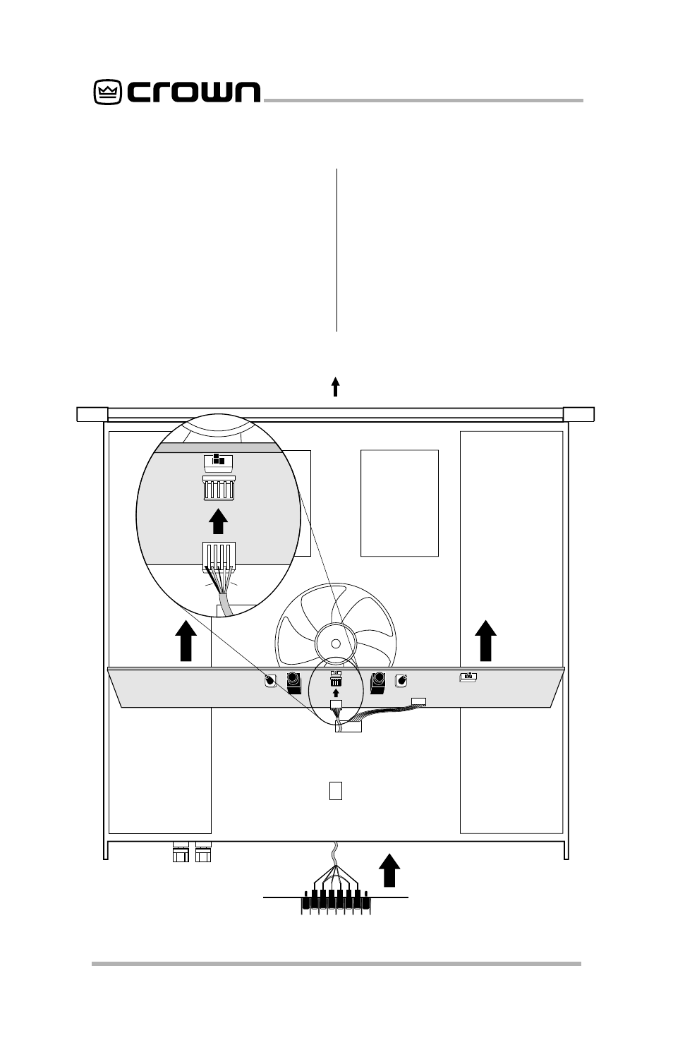
5. Insert the cable of the
MT–BB
through the rear panel opening, and
through the rectangular chassis hole
directly behind the fan.
6. Plug the
MT–BB connector into J1 on
the Main Board. J1 is the five-pin
header located immediately behind
the Ground Lift Switch. The wires at
the connector should face the rear
with the black wire on the left and the
green wire on the right.
7. Fasten the
MT–BB panel in place us-
ing the screws provided and reas-
semble the amplifier by reversing
steps 4 through 2.
IMPORTANT: Check that no wires
impede the fan rotation.
8. Restore power to the unit and read-
just the level controls.
Fig. 2.2 Installing an MT-BB
FRONT
BOTTOM VIEW
J1
ROUTE THE MT-BB CABLE
THROUGH THE RECTANGULAR
HOLE BEHIND THE FAN.
MT-BB
J1
BLACK
GREEN
IMPORTANT:
DO NOT
INSTALL THE
CONNECTOR
UPSIDE DOWN.
- MT-2400 (1 page)
- XTi 4000 (44 pages)
- 402and 602 (28 pages)
- DSi 4000 (1 page)
- S Series (28 pages)
- CTs 4200 USP/CN (2 pages)
- CH3 (2 pages)
- MA-5000i (52 pages)
- Commercial Audio Series (180MA-280MA-1160MA) (24 pages)
- Pulse 2X1100 (1 page)
- Pulse 21100 (22 pages)
- K2 (2 pages)
- XLS-602 E (1 page)
- Macro-Tech 602 (36 pages)
- I-TECH 8000 (2 pages)
- 660A (1 page)
- 5000i (1 page)
- MT 600 (1 page)
- 28M (1 page)
- PT 2.1 (2 pages)
- CTs 8200 USP/CN (2 pages)
- SR-II (1 page)
- CTs 2000 (1 page)
- 4300 (1 page)
- IQ-PIP USP3/CN (2 pages)
- 180A (1 page)
- XLS 402 (40 pages)
- 9000i (1 page)
- I (1 page)
- CL2 (1 page)
- MA-2402 (36 pages)
- CROWN K Series (20 pages)
- M Series (28 pages)
- CE 2000 (28 pages)
- Power Tech x.1 Series (24 pages)
- XTi 1000 (2 pages)
- XLS-802 (1 page)
- D-45 (24 pages)
- Xs1200 (28 pages)
- MA-24X6 (32 pages)
- I-T4000 (1 page)
- CTs 600 (32 pages)
- 12000i (2 pages)
- CDi 4000 (1 page)
- MA-3600VZ (28 pages)