Cma-1 – Crown Audio CMA-1 User Manual
Page 10
10
}
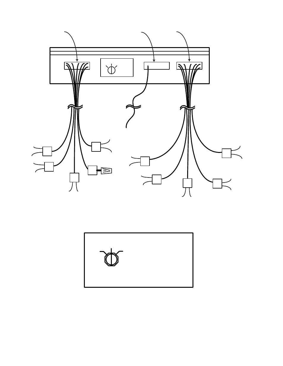
CMA-1
3
4
5
1
3
4
5
SPEAKER
OUTPUTS
REMOTE
INPUTS
Fig. 7 4-Channel Connections
Fig. 8 Switch Position for 4 CH Operation
1
2
4
3
WHITE
CABLES
To CH1
Source
(Left Front)
To CH2
Source
(Right Front)
To CH3
Source
(Left Rear)
Not
Connected
use wire
nut
To CH5
Source
(Right Rear)
BLK/WHT
CH1+
BLK
CH1-
5
2
WHT/RED
CH2+
WHT
CH2-
RED/WHT
CH3+
RED
N/C
Cut and
Tape
GRN/YEL
CH3-
YEL/RED
CH4-
BLU/RED
CH4+
}
CMA-1
3
4
5
CAUTION: Read instruction manual before
operating this switch. Improper installation
could damage vehicle and amplifier.
GRN
N/C
Cut and
Tape
See also other documents in the category Crown Audio Receivers and Amplifiers:
- MT-2400 (1 page)
- XTi 4000 (44 pages)
- 402and 602 (28 pages)
- DSi 4000 (1 page)
- S Series (28 pages)
- CTs 4200 USP/CN (2 pages)
- CH3 (2 pages)
- MA-5000i (52 pages)
- Commercial Audio Series (180MA-280MA-1160MA) (24 pages)
- Pulse 2X1100 (1 page)
- Pulse 21100 (22 pages)
- K2 (2 pages)
- XLS-602 E (1 page)
- Macro-Tech 602 (36 pages)
- I-TECH 8000 (2 pages)
- 660A (1 page)
- 5000i (1 page)
- MT 600 (1 page)
- 28M (1 page)
- PT 2.1 (2 pages)
- CTs 8200 USP/CN (2 pages)
- SR-II (1 page)
- CTs 2000 (1 page)
- 4300 (1 page)
- IQ-PIP USP3/CN (2 pages)
- 180A (1 page)
- XLS 402 (40 pages)
- 9000i (1 page)
- I (1 page)
- CL2 (1 page)
- MA-2402 (36 pages)
- CROWN K Series (20 pages)
- M Series (28 pages)
- CE 2000 (28 pages)
- Power Tech x.1 Series (24 pages)
- XTi 1000 (2 pages)
- XLS-802 (1 page)
- D-45 (24 pages)
- Xs1200 (28 pages)
- MA-24X6 (32 pages)
- I-T4000 (1 page)
- CTs 600 (32 pages)
- 12000i (2 pages)
- CDi 4000 (1 page)
- MA-3600VZ (28 pages)