Slowly open the regulating valve and let in the sf, Shut the regulating valve, Shut the flush valve. filling with test gas – 3B Scientific Critical Point Apparatus User Manual
Page 6: Flushing out air, Onto the gas connec- tion fittings
6
the pipe (more precisely, on the ratio of the pipe
length to the volume of the measuring cell). In the
process, care should be taken that the quantity of the
greenhouse gas SF
6
released in the environment is
reduced to a minimum.
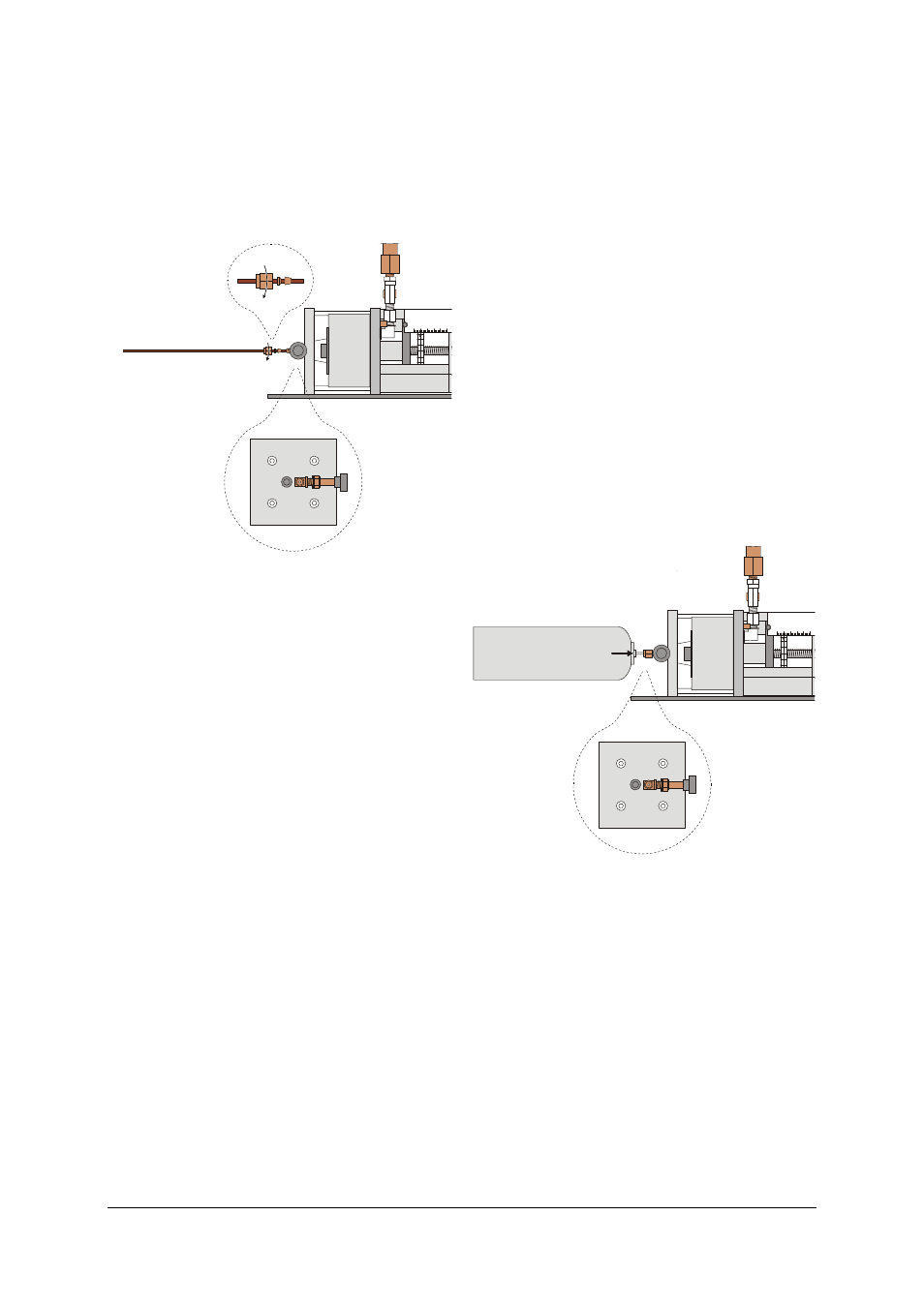
Connecting a fixed pipe:
0 0
1 9
1 8
1 7
1 6
1 5
10
0
20
30
40
50mm
a
b
Fig. 3: Connecting a fixed pipe
(a) flush valve, (b) regulating valve
•
If necessary, pull out the protection for the gas
connection and loosen the valve nut (11 mm) to
remove the 1/8" gas connection fittings.
•
Connect the pipe (if necessary with adapters) to
the gas fitting.
•
Beginning with the valve nut, slide the supplied
screw joints onto the tubing. (See Fig. 3: follow
the sequence and alignment specified along with
the cable binder)
•
Insert the pipe into the regulating valve and
tighten the valve nut till the point is reached
where it is no longer possible to move the pipe
any further using only your fingers.
•
Hold the regulating valve still with an open-end
spanner (13 mm) and tighten the valve nut by a
further 270°.
Now, the connection is gas-tight. When loosening the
valve nut afterwards, the regulating valve also needs
to be held still with a spanner.
Flushing out air:
•
Use the handwheel to set the piston position to
10 mm.
•
Slowly open the regulating valve and let in the SF
6
till a pressure of approx. 10 bar has been at-
tained.
•
Shut the regulating valve.
•
Open the flush valve slightly till the pressure has
dropped to almost 0 bar.
•
Shut the flush valve.
Filling with test gas:
•
After at least four flush cycles, open the regulat-
ing valve till the pressure attained is once again
10 bar.
•
Shut the regulating valve.
•
Turn the handwheel in the reverse direction till
the piston reaches a position of say 46 mm.
•
Slowly open the regulating valve and shut it again
when a pressure of 10 bar has been attained.
7.3 Filling with gas from a MINICAN®:
Additionally required:
1 MINICAN® gas container with SF
6
, e.g. from the
company Westfalen (www.westfalen-ag.de
If the equipment is used only occasionally, it is more
practical to draw the test gas from a MINICAN® gas
container. The gas connection of a MINICAN® con-
tainer is similar in design to a commercial spray can,
i.e. it opens when the MINICAN® container is pressed
directly onto the gas connection fittings.
Here too, filling begins with several rinsing cycles for
flushing out the air.
0 0
1 9
1 8
1 7
1 6
1 5
10
0
20
30
40
50mm
SF
6
a
b
Fig. 4: Filling with test gas from a MINICAN® gas container
(a) flush valve, (b) regulating valve
Flushing out air:
•
If necessary, pull off the protection for the gas
connection.
•
Use the handwheel to set the piston position to
10 mm.
•
After removing the protective cap, position the
MINICAN® container with SF
6
onto the gas connec-
tion fittings.
•
Press the MINICAN® container onto the gas con-
nection fittings, slowly open regulating valve (b)
and let in SF
6
till a pressure of approx. 10 bar has
been attained.
•
Shut the regulating valve.