3B Scientific Teltron NMR Supplementary Set User Manual
Page 3
3
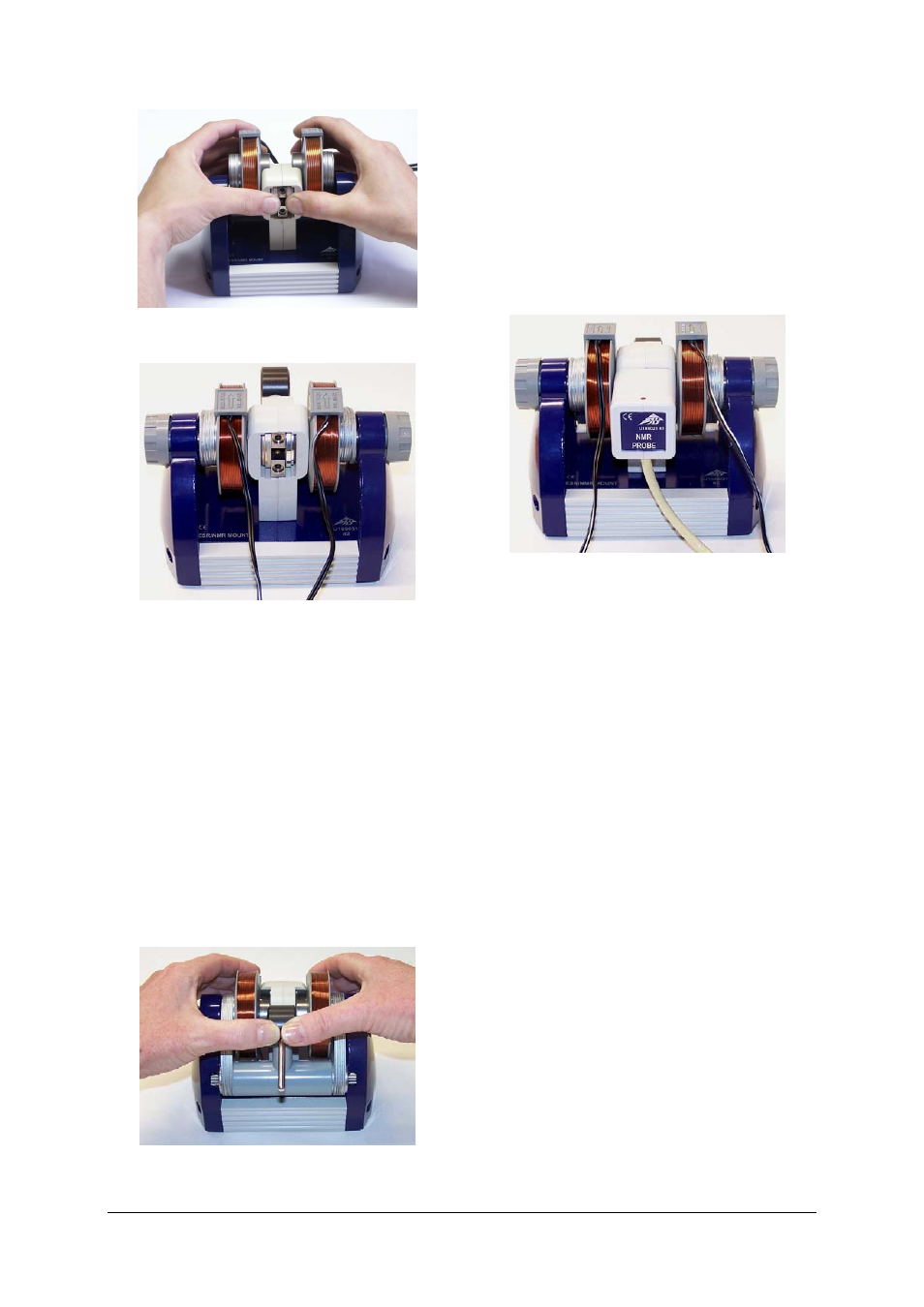
Fig. 5 Pulling the magnets onto the assembly discs
Fig. 6 Basic unit completed with permanent magnets
and coils
7.1.1 Removing magnet unit
• Take the sample out of the sample chamber
in the basic unit.
• Disconnect the cables between the coils and
the control console.
• Loosen the knurled screws.
• Turn the basic unit so that the magnet unit is
pointing forwards.
• Lift up the yoke till it is on top of the sample.
• Hold the yoke in place with your thumbs and
use your fingers to pull the magnet unit to-
wards the front till the yoke is between the
two magnets. Then take the entire unit out of
the basic unit (see Fig. 7).
• Take the discs out of the sample chamber.
Fig. 7 Removing the magnet unit from the basic unit
7.2 Connection to control console
• Insert the probe into the sample chamber in
such a way that it rests on the housing (see
Fig. 8).
• Connect the cable for the probe to the
“Probe In” socket of the control console, tak-
ing note of the socket's slot.
• Connect the coils to the “Coil” sockets on
the back of the control console.
• Connect the control console to its power
supply via the “12 VAC/1A“ socket.
Fig. 8 Basic unit with probe
7.3 Calibration and settings
7.3.1 Using an oscilloscope
• Connect the “SIGNAL OUT” socket of the
control console to channel 1 of the oscillo-
scope and the “FIELD OUT” output to chan-
nel 2 (see Fig. 12).
• Set the oscilloscope as follows:
Channel 1: 0.5 V DC
Channel 2: 0.5 V DC
Time base: 5 ms
Trigger from a falling edge on channel 1.
7.3.2 Using 3B NETlog™
• Connect the “SIGNAL OUT” socket of the
control console to input
IN
B
U
on the 3B NET-
log
™ unit and “FIELD OUT” to the input
IN
A
U
.
• Connect the 3B NETlog™ unit to a computer
and run the 3BNETlab
TM
software
• Create a new data record from the “Meas-
urement lab” menu and define the following
parameters:
Input A: Field, Input mode VDC, Input range 2 V
Input B: Signal, Input mode VDC, Input
range 2 V
Measurement interval: 500 µs (2 kHz)
• Set to trigger from Input A with a falling edge
and a positive trigger point at about 10 to 20%.
• Activate the “Oscilloscope” button and start
measuring.
The oscilloscope window will open.