3B Scientific Teltron NMR Supplementary Set User Manual
Page 2
2
6. Equipment required in addition
1 ESR/NMR basic set (230 V, 50/60 Hz) 1000638
or
1 ESR/NMR basic set (115 V, 50/60 Hz) 1000637
1 Analogue oscilloscope, 2x30 MHz 1002727
2 High-frequency cables
1002746
alternatively
1 3B NETlog™ unit (230 V, 50/60 Hz) 1000540
or
1 3B NETlog™ unit (115, 50/60 Hz) 1000539
1 3B NETlab™ 1000544
2 High-frequency cables, BNC/4-mm plug 1002748
1 PC
7. Operation
7.1 Assembly of the basic unit
The discs, the pole surfaces of the magnets and
the probe chamber in the basic unit must all be
free of grease, dust and debris.
• If necessary they should be cleaned using
isopropanol.
• Insert the discs into both sides of the sample
chamber (see Fig. 1).
Fig. 1 Sample chamber with assembly discs inserted
• Twist the metal rod into the yoke of the
magnet unit. Place the magnet unit in the
clip on the basic unit as shown in Fig. 2.
• Take the magnet unit in both hands and push
the yoke downwards with your thumbs (see
Fig. 3).
• Push the coils over the magnets, making
sure the direction if the windings is the
same. The embossed arrows on the coils
must point in the same direction.
• Clean any grit or metal shavings off the two
magnets with a cloth.
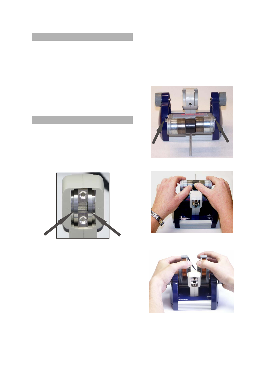
• Move the completed magnetic unit onto the
assembly discs, making sure to carry out the
steps that follow: (see Fig. 4).
• Separate the two coils with your hands, pull-
ing them outwards to increase the gap be-
tween them. You can rest your hands on the
knurled screws while doing this. Push the
magnets about a quarter of the way onto the
assembly discs (see Fig. 4).
• Push back the two discs with your thumbs and
pull on the coils to move the magnet supports
into their end positions (see Fig. 5).
• Tighten both knurled screws by hand at the
same time. Make sure that the magnets are
accurately aligned on top of the assembly
discs. If necessary, slot the discs all the way
back into the probe chamber and then push
the magnet supports into their end positions.
Fig. 2 Permanent magnet inserted into basic unit
Fig. 3 Removing the yoke from the permanent mag-
net
Fig. 4 Pulling the two permanent magnets apart