3B Scientific Heat Pump D (115 V, 60 Hz) User Manual
Page 4
4
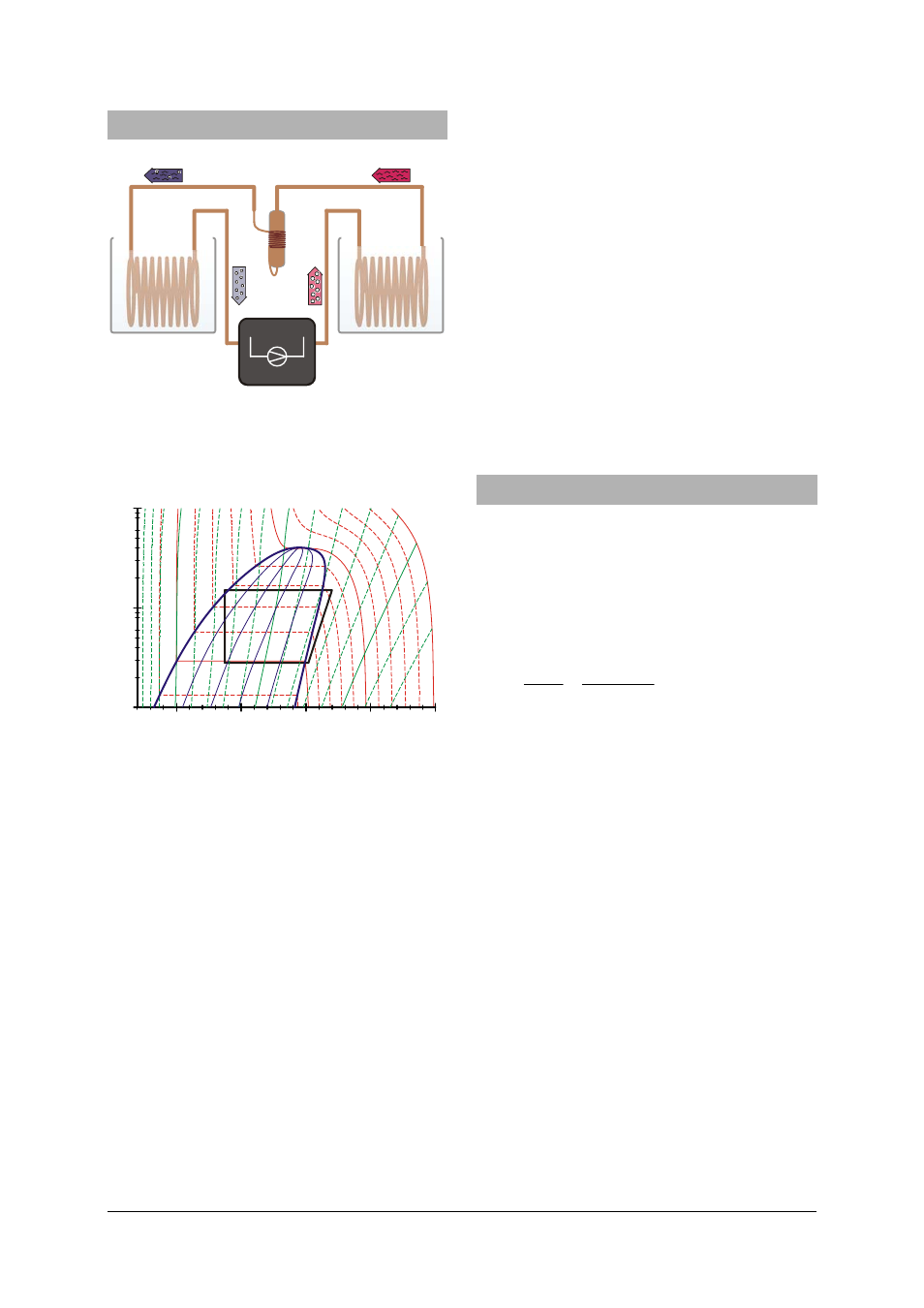
7. Heat pump cycle
1
4
2
3
Fig. 4 Schematic diagram of the heat pump with
compressor (1→2), condenser (2→3), ex-
pansion valve (3→4) and evaporator (4→1)
1.
0
1.
5
S / kJ/kg K
T
2.
0
600
500
H / kJ/kg
p / mbar
400
300
1
2
3
4
200
0.1
1
10
200°C
100°C
0°C
Fig. 5 Mollier diagram of ideal heat cycle (see sec-
tion 7)
The idealised version of the heat pump cycle
involves four steps: compression (1→2), lique-
faction (2→3), controlled expansion (3→4) and
vaporisation (4→1):
Compression:
The gaseous refrigerant is sucked in by the com-
pressor without changing the entropy (s
1
= s
2
). It
is then compressed from pressure p
1
to p
2
which
causes excess heat to be generated. The tem-
perature rises from T
1
to T
2
. The mechanical work
done per unit mass is Δw = h
2
– h
1
.
Liquefaction:
The fluid cools sharply inside the condenser caus-
ing it to liquefy. The heat emitted by this process
(latent heat) heats up the surrounding reservoir to
temperature T
2
. The change in heat per unit mass
is Δq
2
= h
2
– h
3
.
Controlled expansion:
The condensed refrigerant reaches the expansion
valve where it is allowed to expand to a lower
pressure without any mechanical work being done.
This results in a drop in temperature since work
needs to be done against the force of attraction
between refrigerant molecules (Joule-Thomson
effect). Enthalpy remains constant (h
4
= h
3
).
Vaporisation:
In the evaporator, the refrigerant absorbs heat and
vaporises completely. This causes the surrounding
reservoir to cool to a temperature T
1
. The heat
absorbed per unit mass is Δq
1
= h
1
– h
4
.
The vaporised refrigerant is sucked back in
again by the compressor to start the compres-
sion process anew.
8. Example experiments
8.1
Efficiency of the compressor
The efficiency of the compressor η
co
is given by
the ratio of the change in energy ΔQ
2
provided
to the warm water reservoir per unit time Δt, to
the power P supplied to the compressor to per-
form its work. It decreases as the temperature
difference between the condenser and the
evaporator increases.
t
P
T
m
c
t
P
Q
Δ
⋅
Δ
⋅
⋅
=
Δ
⋅
Δ
=
2
2
co
η
c
= specific heat capacity of water and
m
= mass of water.
Determining the efficiency:
•
Connect the heat pump to the mains supply.
•
Fill up the water containers with 2000 ml
water and mount them into the retaining
plates.
•
Allow the compressor to run for about 10
minutes before starting the experiment until
it reaches its operating temperature.
•
Then fill up the water containers again and
mount the two thermometers into the hold-
ers at the water containers.
•
Stir the water in the containers thoroughly
throughout the experiment.
•
Determine and note the initial temperature in
both water containers.
•
Push the button „Zeit“ (time) at the energy
monitor 2x and at the same time switch
•
Read off the power consumed so far and the
temperatures in the two water reservoirs at
regular intervals and make a note of them.