3B Scientific Heat Pump D (115 V, 60 Hz) User Manual
Page 3
3
3. Description
The Heat Pump D is a demonstration model for
showing how refrigerators and electrical com-
pression heat pumps work. It consists of a com-
pressor with a drive motor, a condenser, an
expansion valve and an evaporator and can be
operated as a water-air or water-water heat
pump.
The components are connected in a closed sys-
tem by copper pipes and mounted on a base
board, and the clear layout makes it possible to
directly relate the sequence of changes of state
to the cyclic operation of the heat pump.
Evapo-
rator and condenser are constructed as copper
tubing spirals and each of them is submerged in
water filled containers serving as heat reservoirs
for determining the heat absorbed or emitted.
Two analog thermometers are supplied, which
allow the necessary temperature measurements
to be made in both water reservoirs
.
Two observation windows are provided for ob-
serving the state of aggregation of the refriger-
ant after the evaporator and after the condenser.
Two large manometers indicate the pressure
before and after the safety valve. The mains
connector incorporates a digital energy meter for
determining the period of operation, the mains
voltage, the current power consumption and the
amount of electrical work done. A protective
overpressure switch disconnects the compres-
sor motor from the circuit when overpressure
reaches 15 bars.
The heat pump D is available for two different
mains voltages. 1000820 is designed for 230 V
(±10 %), 50 Hz mains supplies, while the
1000819 model is for 115 V (±10 %), 60 Hz sup-
plies.
4. Accessories
A Pt 100 thermocouple with measurement ter-
minal (1009922) is ideal for measuring the tem-
perature at various places along the copper
piping, since it can be clamped directly to the
copper and provides good thermal conduction
between the pipe and the sensor. It can be used
in conjunction with the 3B NETlog “Datalogger”.
Fig. 2 Pt 100 thermocouple with measurement
terminal
5. Technical data
Compressor power:
120 W, dependent on
operating state
Refrigerant:
R 134A
(tetrafluorethane
C
2
H
2
F
4
)
Boiling point:
-26°C at 1 bar
Water reservoirs:
2000 ml each
Manometer:
160 mm diam., up to 9
bars (low-pressure side,
suction intake), up to 24
bars (high-pressure side,
pressure pipe)
Excess pressure cut-off: disconnects compressor
from the mains at 15 bars
Power supply:
115 V, 60 Hz or
230 V, 50 Hz
Dimensions:
750 x 350 x 540 mm³
Weight:
approx. 21 kg
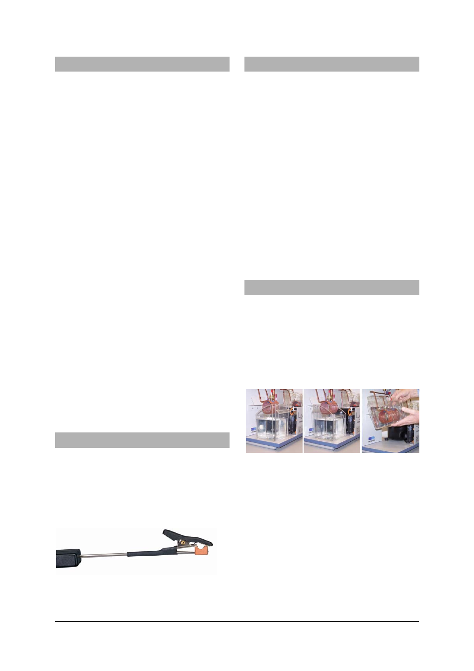
6. Operation
6.1 Filling the water containers
•
Fill up the water containers with water and
move them with the low edge first under the
evaporator and the condenser.
•
Turn the beakers in such a way that the high
edge points to the back wall.
•
Lift up the beakers and mount them into the
retaining plates.
Fig. 3 Connection of the water reservoirs to the
heat pump
Left: reservoir with its lower edge facing the pump
Centre: reservoir turned with its lower edge facing the
front
Right: reservoir suspended in holding plate
6.2 Configuration
•
Allow the heat pump to stand upright for at
least 7 h before using it if it was tipped over.
•
To start the pump, fill the two water reservoirs
and connect the pump to the mains.
•
Turn on the compressor.
Note: the energy meter works even when the
compressor is switched off.