Ironwood Electronics Gull Wing Surface Mount Foot Soldering Instructions User Manual
Page 3
Page 3 of 4
GSI.doc, Rev. C
Gull wing Surface mount Foot Soldering Instructions (continued)
Tel: (800) 404-0204
www.ironwoodelectronics.com
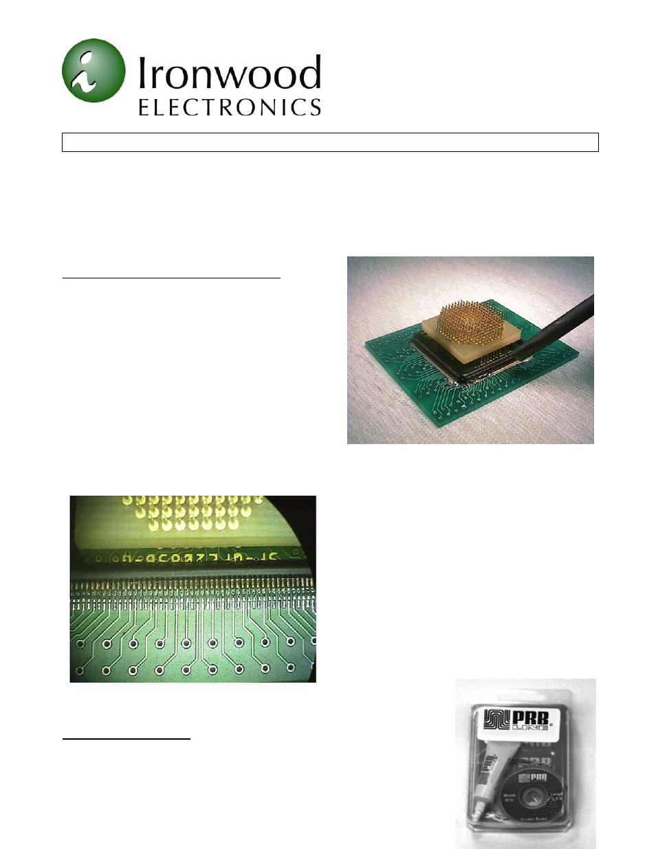
(e) Reflow, with a hot air wand/gun, the solder over a few of the pads in opposite corners (diagonally) of the land
pattern (Figure 6).
(f) Check the foot alignment.
(g) Continue by reflowing the remaining solder paste. Add or remove solder as needed (see step (f) in method
1.).
SOLDERING IRON - Soldering method #3
This method has produced very good results but may be
more time consuming than the other two methods.
Caution must be used when touching the soldering iron
tip to the emulator foot. Excessive heat or pressure may
damage the pads on the side of the foot.
(a) Using a small diameter solder wire (approx. 0.015" or
smaller) and a very fine tipped soldering iron, add enough
solder to two opposite corner (diagonal) pads to cover
them.
(b) Align and place the emulator foot over the QFP land
pattern (see steps (c) and (d) in method 1).
(c) Holding the foot in place, by pressing down gently on
the gold terminal pins, place the iron tip on the two pads
to reflow the solder. This will tack and keep the foot in
alignment.
(d) Under a microscope or magnifying lens, if available, solder the remaining edge pads of the foot to the target
PCB land pattern using a liberal amount of solder (shorts
between adjacent pads can be removed later).
(e) Apply a generous amount of flux along the side of the
foot.
(f) Tilt the PCB and emulator foot at 30 - 45 degree
angle. Start at one corner and pull the tip of the iron
along the side of the foot to remove excess solder
deposits. Clean the tip of the iron often. Repeat this step
several times starting at a point on the foot ahead of the
excess solder. Continue along the side of the foot until
shorts are removed and a fillet is present between feet
and target PCB pads.
(g) Repeat steps (e) and (f) for the remaining three sides.
The finished solder connections are shown in Figure 7.
Removing or Desoldering
Conventional methods can be used to remove a surface mount foot from your
target board, however we recommend the use of PRB Line® D’SOLDER™.;
This SMT device removal product avoids the use of excessive heat that can
compromise the integrity of our product and your target board. The specially
Figure 6: Reflow using hot air tool
Figure 7: Finished Solder Fillets