Of the bisected pad – Ironwood Electronics Kelvin testing using GHz socket User Manual
Page 3
Tel: (800) 404-0204
www.ironwoodelectronics.com
of the bisected pad.
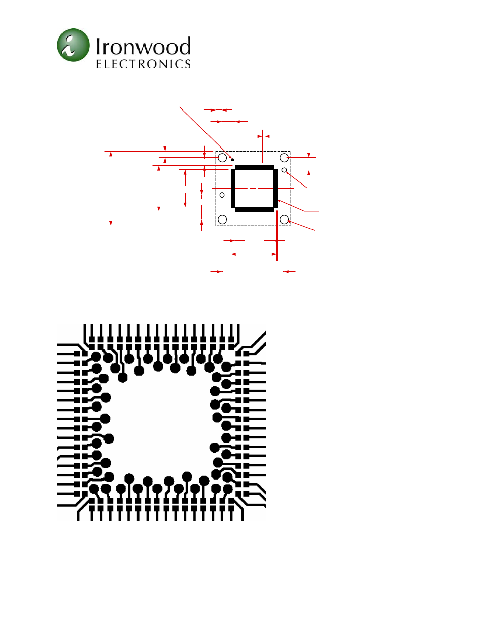
15.225mm±0.125mm sqr.
Socket size
Orientation Mark
No n plated mounting hole
No n plated alignment hole
2.72mm*
1.68mm
0.5mm typ.
5.08mm
2.54mm
12.725mm±0.125mm (x4)
0.69 x 0.28 mm
9.36mm
9.36mm
7.78mm
7.78mm
1.25mm±0.125mm (x4)
1.25mm±0.13mm (x4)
Ø 1.61mm
+
-
0.050mm
0.050mm
(x4)
Ø 0.85mm
+
-
0.025mm
0.025mm
(x2)
pad (x 64)
MLF64A
Figure 3A: Suggested PCB layout for SG-MLF-7008
Figure 3B: Split pad layout
For our purposes, an SG-MLF-7008 was used with a 64-position MLF test chip. The chip
was set up in a daisy chain pattern and provides a resistance through spiral circuitry from
bottom to top of board (Figure 4). The target board allows Kelvin connections to every pin.
The results are shown below in Fig. 5.