Plugnplay, Smart ride, Installation – Airbagit Smart Ride User Manual
Page 3: Complete digital air management system
2
A I R B A G I T. C O M S U S P E N S I O N S
2 6 0 S . H I B B E R T, M E S A , A Z P H . 8 0 0 - 8 4 2 - 8 7 8 9
Smart Ride
COMPLETE DIGITAL AIR MANAGEMENT SYSTEM
Smart Ride
COMPLETE DIGITAL AIR MANAGEMENT SYSTEM
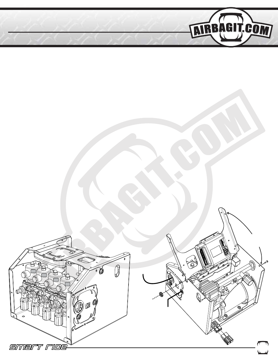
REMOVE SCREWS AND
ROTATE TOP BRACE TO
GAIN ACCESS TO THE
SMART-RIDE RELAY
CONTROL BOX
ROUTE HEIGHT SENSOR
LOOMS AND LCD
CONTROLLER CABLE
THROUGH GROMMET
ROUTE AIRBAG AIRLINES
THROUGH LARGE GROMMET
CHECKED VALVE INLET
PLUMB TO TANK
PLUG MAIN POWER
HARNESS IN BEFORE
CONNECTING THE LCD
CONTROLLER
FR
RL
FL
RR
PlugnPlay
INSTALLation
1. Disconnect the negative battery terminal.
2. Remove top of Plug n Play by removing external screws with supplied bit.
3. Mount the Plug n Play in a dry location. It is recommended that you leave 5.5”-6” of room free in front of the PnP
for valve removal.
4. Install tank and connect a line to the tank from the compressor and a second line back to checked inlet of the
PnP.
5. Route Airbag airlines through the large grommet and connect to the valves. See figure below for valve assign-
ments.
6. Run 8 gauge power wire to the battery and connect through the supplied 60Amp brearker. Also, make sure the
ground wire is connected to a clean part of the frame.
7. Connect the Smart-Ride’s White wire to the cars ignition.
8. Locate a safe position for the LCD controller to be mounted. The controller can also remain loose and be hand-
held. Make sure the controller isn’t in a position where it can be accidentally activated while driving.
9. Route the LCD controller wire loom from the controller to the Plug n Play. The loom will pass through the small
plastic grommet in the middle top of the Plug n Play. Do not plug LCD loom into the Relay control box yet.
10. Plug the Red and Black power connection into the Plug n Play.
11. Connect the vehicles battery.
12. Plug the LCD Controller into the Relay control box. The LCD display will turn on the run through its intialization
process. Once the LCD turns on the compressor will start filling the tank. The display will show the tank pressure
and the individual bag pressures. The height sensor will not display until they are connected.
13. Test the valves to make sure they are connected correctly.
14. Mount the height sensors (See Height Sensor Installation Section) and route wires through the
same grommet as the LCD loom. The height display for each corner will activate when the height sensor is
connected to the relay control box.
15. (Optional) Connect necessary “Optional Input Loom” to the third party controller. +12V Only
16. Calibrate the height sensors. (See Calibration Section).
17. Reinstall Plug n Play Top.