11 en – PowerWalker VFI 20000TP 3_3 BX User Manual
Page 17
11
EN
for each group being168VDC-192VDC. Battery capacity and number of group can be se-
lected at your option. Battery pack must be equipped with DC switch (it is suggested that
selection of DC switch should be in line with installation drawing for wire connection).
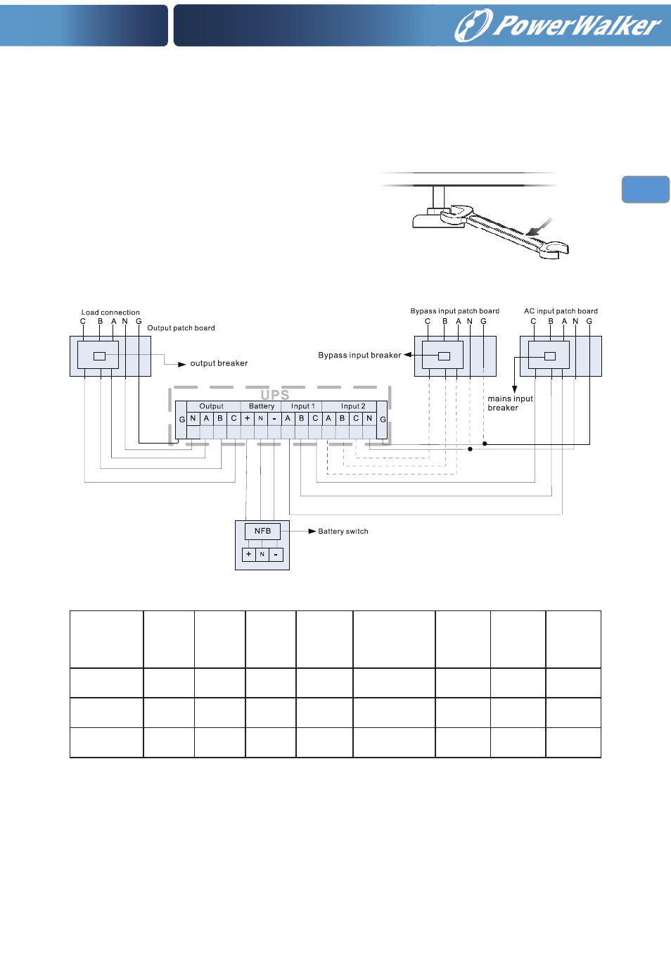
9) Installation and wire connection diagram
10) Jumper list for the UPS
8) Brake pad: use wrench 19# in clock-
wise direction so as to screw the brake
pad down to the ground, keeping the
machine from moving.
(Optional kit)
Machine
Model
Rated
power
input live
wire
Diameter
Input
switch
Output live
wire
Diameter
Battery positive
and negative
wire Diameter/
battery Diameter
Ground
wire
Diameter
Output N
wire
Diameter
Battery
switch
VFI 20000TP
3/3 BX
20KVA/
16KW
10AWG/
6mm
2
3Φ63A/
380VAC
10AWG/
6mm
2
8AWG/
10mm
2
8AWG/
10mm
2
8AWG/
10mm
2
3Φ125A/
250VAC
VFI 30000TP
3/3 BX
30KVA/
24KW
8AWG/
10mm
2
3Φ63A/
380VAC
8AWG/
10mm
2
6AWG/
16mm
2
6AWG/
16mm
2
6AWG/
16mm
2
3Φ150A/
250VAC
VFI 40000TP
3/3 BX
40KVA/
32KW
6AWG/
16mm
2
3Φ63A/
380VAC
6AWG/
16mm
2
4AWG/
25mm
2
4AWG/
25mm
2
4AWG/
25mm
2
3Φ200A/
250VAC