Current-mode control loop – Rainbow Electronics MAX5095A User Manual
Page 12
MAX5094A/B/C/D/MAX5095A/B/C
Current-Mode Control Loop
The advantages of current-mode control over voltage-
mode control are twofold. First, there is the feed-forward
characteristic brought on by the controller’s ability to
adjust for variations in the input voltage on a cycle-by-
cycle basis. Secondly, the stability requirements of the
current-mode controller are reduced to that of a single-
pole system unlike the double pole in the voltage-mode
control scheme.
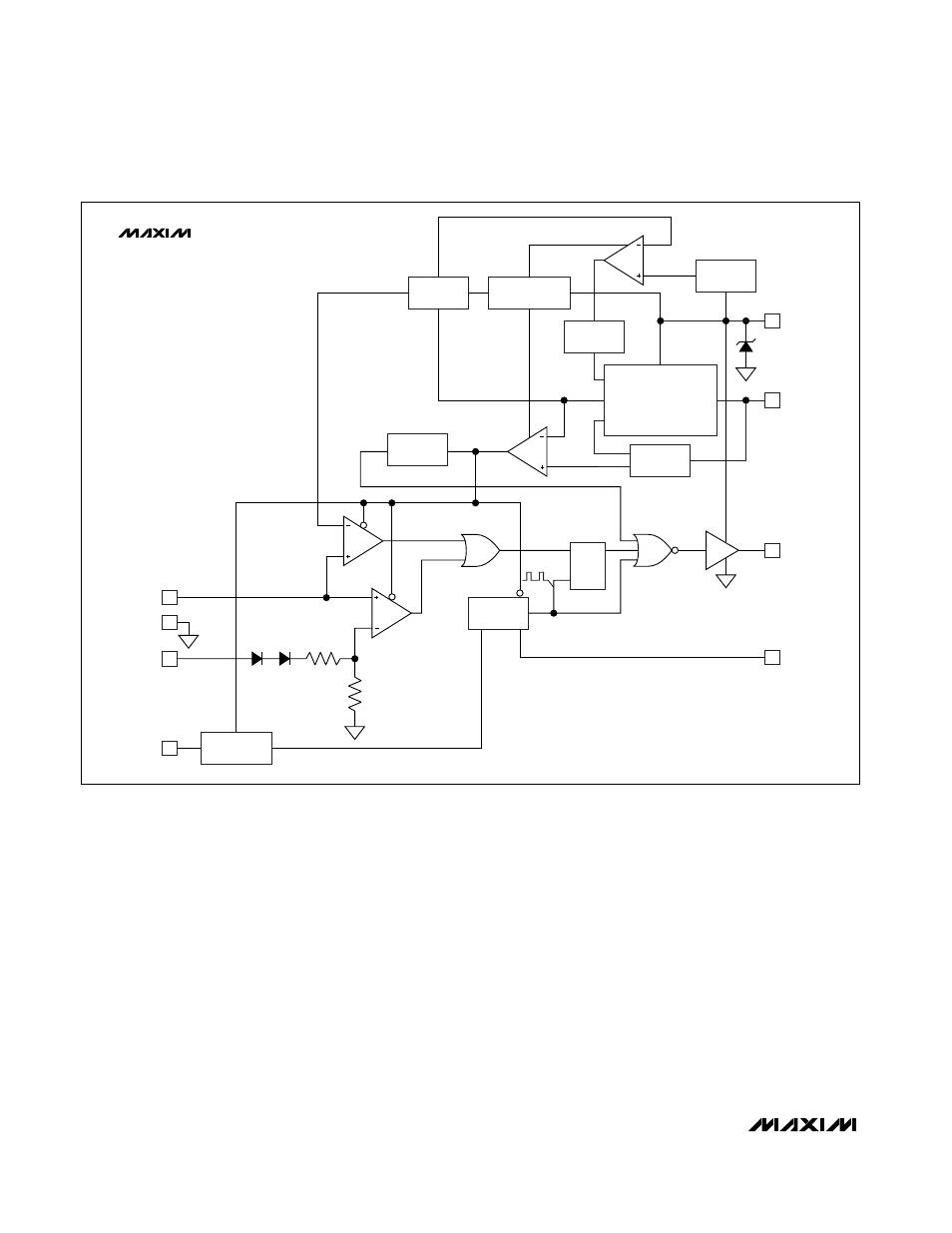
The MAX5094/MAX5095 use a current-mode control loop
where the output of the error amplifier is compared to the
current-sense voltage (V
CS
). When the current-sense sig-
nal is lower than the inverting input of the CPWM com-
parator, the output of the comparator is low and the
switch is turned on at each clock pulse. When the cur-
rent-sense signal is higher than the inverting input of the
CPWM comparator, the output is high and the switch is
turned off.
High-Performance, Single-Ended, Current-Mode
PWM Controllers
12
______________________________________________________________________________________
UVLO
REFERENCE
2.5V
PREREGULATOR
5V
VOLTAGE-
DIVIDER
THERMAL
SHUTDOWN
EN-REF
BG
SNS
V
DD
5V REGULATOR
VOLTAGE-
DIVIDER
8
7
26.5V
V
CC
REF
2.5V
VP
REG_OK
DELAY
S
R
Q
OSC
Q
4 R
T
/C
T
6 OUT
ILIM
CPWM
0.3V
EN-DRV-BAR
R
2R
3
5
1
2
CS
GND
COMP
SYNC
CLK
MAX5095A
MAX5095B
VP
2.5V
BIDIRECTIONAL
SYNC
100% MAX DUTY CYCLE (MAX5095A)
50% MAX DUTY CYCLE (MAX5095B)
8.4V/7.6V
Figure 2. MAX5095A/B Functional Diagram