Detailed description – Rainbow Electronics MAX5095A User Manual
Page 11
Detailed Description
The MAX5094_/MAX5095_ current-mode PWM con-
trollers are designed for use as the control and regulation
core of flyback or forward topology switching power sup-
plies. These devices incorporate an integrated low-side
driver, adjustable oscillator, error amplifier (MAX5094_
only), current-sense amplifier, 5V reference, and external
synchronization capability (MAX5095A/MAX5095B only).
An internal +26.5V current-limited V
CC
clamp prevents
overvoltage during startup.
Eight different versions of the MAX5094/MAX5095 are
available as shown in the Selector Guide. The
MAX5094A/MAX5094B are the standard versions with a
feedback input (FB) and internal error amplifier. The
MAX5095A/MAX5095B include bidirectional synchroniza-
tion (SYNC). This enables multiple MAX5095A/
MAX5095Bs to be connected and synchronized to the
device with the highest frequency. The MAX5095C
includes an ADV_CLK output, which precedes the
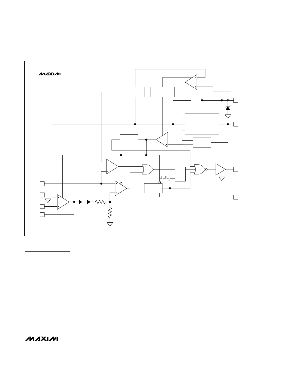
MAX5095C’s drive output (OUT) by 110ns. Figures 1, 2,
and 3 show the internal functional diagrams of the
MAX5094_, MAX5095A/MAX5095B, and MAX5095C,
respectively. The MAX5094A/MAX5094C/MAX5095A are
capable of 100% maximum duty cycle. The MAX5094B/
MAX5094D/MAX5095B/MAX5095C limit the maximum
duty cycle to 50%.
MAX5094A/B/C/D/MAX5095A/B/C
High-Performance, Single-Ended, Current-Mode
PWM Controllers
______________________________________________________________________________________
11
UVLO
REFERENCE
2.5V
PREREGULATOR
5V
VOLTAGE-
DIVIDER
THERMAL
SHUTDOWN
EN-REF
BG
SNS
V
DD
5V REGULATOR
VOLTAGE-
DIVIDER
8
7
26.5V
V
CC
REF
2.5V
VP
REG_OK
DELAY
S
R
Q
OSC
Q
4 R
T
/C
T
6 OUT
ILIM
CPWM
1V (MAX5094A/B)
0.3V (MAX5094C/D)
EN-DRV-BAR
R
2R
VEA
3
5
2
1
CS
GND
FB
COMP
CLK
MAX5094_
VP
2.5V
8.4V/7.6V
100% MAX DUTY CYCLE (MAX5094A/MAX5094C)
50% MAX DUTY CYCLE (MAX5094B/MAX5094D)
Figure 1. MAX5094_ Functional Diagram