Applications, Micropower step-down converter, High-current step-down converter – Rainbow Electronics MAX1627 User Manual
Page 13
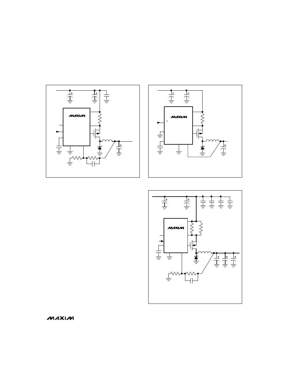
________________________Applications
The MAX1626/MAX1627 typical operating circuits
(Figures 1 and 8) are designed to output 2A at a 5V
output voltage. The following circuits provide examples
and guidance for other applications.
Micropower Step-Down Converter
When designing a low-power, battery-based applica-
tion, choose an external MOSFET with low gate capaci-
tance (to minimize switching losses), and use a low
peak current limit to reduce I
2
R losses. The circuit in
Figure 9 is optimized for 0.5A.
High-Current Step-Down Converter
The circuit in Figure 10 outputs 6A at 2.5V from a 5V or
3.3V input. High-current design is difficult, and board
layout is critical due to radiated noise, switching tran-
sients, and voltage gradients on the PC board traces.
Figure 11 is a recommended PC board design. Choose
the external MOSFET to minimize R
DS(ON)
. Keep the
gate-charge factor below the MAX1626/MAX1627’s
drive capability (see Ext Rise and Fall Times vs.
Capacitance graph in the
Typical Operating
Characteristics). Otherwise, increased MOSFET rise
and fall times will contribute to efficiency losses. For
higher efficiencies, especially at low output voltages,
the MAX796 family of step-down controllers with syn-
chronous rectification is recommended.
MAX1626/MAX1627
5V/3.3V or Adjustable, 100% Duty-Cycle,
High-Efficiency, Step-Down DC-DC Controllers
______________________________________________________________________________________
13
MAX1627
C5
0.47
µ
F
P
D1
R
SENSE
0.15
Ω
U1
LOGIC-LEVEL MOSFET
C4
0.1
µ
F
OUT
N.C.
SHDN
REF
V+
EXT
CS
GND
FB
INPUT
L1
22
µ
H, 3A
R3
R2
C
R2
C1
220
µ
F
LOW-ESR
TANTALUM
C2
68
µ
F LOW-ESR
TANTALUM
C3
68
µ
F LOW-ESR
TANTALUM
L1: SUMIDA CDRH125-220
D1: NIHON NSQ03A03
U1: MOTOROLA MMSF3P02HD
ADJUSTABLE
OUTPUT
Figure 8. MAX1627 Typical Operating Circuit
MAX1626
C3
0.47
µ
F
P
D1
R
SENSE
0.15
Ω
U1
LOGIC-LEVEL MOSFET
C4
0.1
µ
F
3/5
SHDN
REF
V+
EXT
CS
GND
OUT
INPUT
L1
68
µ
H, 0.7A
OUTPUT
C1
100
µ
F
LOW-ESR
TANTALUM
C2
68
µ
F LOW-ESR
TANTALUM
L1: SUMIDA CDR1053-680
D1: MOTOROLA MBRS130T3
U1: MOTOROLA MMSF3P02HD
Figure 9. 0.5A Step-Down Converter
MAX1627
P
OUTPUT
2.5V, 6A
R3
21.5k, 1%
R2
20k, 1%
D1
C
R2
220pF
Q1
LOGIC-LEVEL MOSFET
C10
0.1
µ
F
OUT
3V TO 6V
SHDN
N.C.
REF
V+
EXT
CS
GND
FB
INPUT
L1
2.7
µ
H >8A
C4
100
µ
F
C5
100
µ
F
C9
1.0
µ
F
R
CS1
, R
CS2
0.025
Ω
C8
1.0
µ
F
C7
0.1
µ
F
C3
220
µ
F
C2
220
µ
F
C1
220
µ
F
C6
0.1
µ
F
C1–C3: SANYO OS-CON 220
µ
F,
6.3V
C4, C5: SANYO OS-CON 100
µ
F,
20V
RCS1, RCS2: 0.025
Ω
DALE WSL-2512
Q1: MOTOROLA MTB50PO3HDL
D1: NIEC C10T04Q
L1: SUMIDA CDRH127-2R7NC
Figure 10. 6A Step-Down Converter